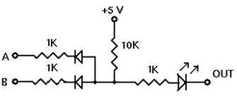
This AND gate circuit takes either high (5V) or low (0V) inputs and generates an output.
Due to this circuits construction, an unconnected input behaves as a high, not as a low (like one might think).
So in your simulation you are inputting either high (unconnected) or high (5V) but never inputting a low (0V).
If your inputs are always high you aren't going to ever get anything but high on the output.
Just connect the switches to ground and your simulation will be fixed.
In general the diode needs to point to a lower voltage to get any current flow across it. And the voltage drop needs to be in the 0.6V~0.7V range to get any significant current.
Assuming 2V across the LED and no current in the didoes, the voltage at the left side of R4 is...
2V + (5V - 2V) * 1K / 11K = 2.27V.
Therefore the inputs must be connected to a voltage below 1.57V (2.27 - 0.7V) before you will start to see much change in current at either the diodes or the LED.

