1
\$\begingroup\$

enter image description here

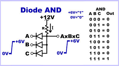
The explanation (from https://en.wikipedia.org/wiki/Diode_logic) states that

R is connected to +12 volts to provide the forward bias current for the diodes and current for output drive. If all inputs A AND B AND C are a positive voltage (+6 volts here), current flowing through R will pull the output positive till the diodes clamp the output to +6 volts, the logical 1 output level. If any input switches to 0 volts (logical 0 level), current flowing through the diode will pull the output voltage down to 0 volts. The other diodes would be reverse biased and conduct no current.

Why the explanation says that R is connected to 12 V? Is the 12V obligatory given "1" is 6V? What are the Kirchhoff equations for this... well it is not a circuit. Is this a kind of star topology connection? What is the mathematical nature/description of this? What exactly does clamp mean - does this mean diodes connected in parallel with cathodes to input, anodes to output will sink all the voltage until it is equal to minimum of their input?

\$\endgroup\$
1
  • \$\begingroup\$ it's not a circuit? Well, the full circuit isn't drawn. Implied is a 0v connection, which all the voltages are referenced to, and the input diodes sink current to when the inputs are '0', and a battery to supply the +12v. Draw those, and you have your circuit. \$\endgroup\$
    – Neil_UK
    Commented Oct 27, 2017 at 9:28

1 Answer 1

2
\$\begingroup\$

There is more than just logic going on in this circuit due to using that +12 V. If that was +6 V things would be more clear I guess.

Fact is that all 3 inputs are either 0 V or 6 V. When only one of the inputs is 0 it "overrules" the others and pulls the output low. This is the logic AND function. All have to be +6V for the output to be 6 V as well.

Why 6 V and not 12 V?

Because the diodes will not allow it, the output voltage is "clamped".

For there to be +12 V at the output all diodes would have to be non-conducting. This can only happen when all 3 input voltages are +12 V.

Since the inputs are defined to be either 0 V or +6 V, this (all three inputs at +12 V) is never going to happen so the output will never be +12 V. It can only reach +6 V.

well it is not a circuit

What would you call it then? In my opinion a circuit consists of at least two components having at least one common connection. So I'm quite sure that this is a circuit.

And I'm even more sure that Kirchoff's laws still apply.

But rather than "throwing" Laws and formulas at circuit (which I often see beginners do) I look at the circuit and ask myself "What happens here".

\$\endgroup\$
9
  • \$\begingroup\$ Thank you. Is the resistor necessary in this design? Could there be nothing instead of it? If it is what is the exact meaning of it's resistance in terms of this gate to work? \$\endgroup\$
    – 4pie0
    Commented Oct 27, 2017 at 9:13
  • \$\begingroup\$ Imagine what happens if the resistor was gone. If all the diodes were non-conducting what would be the voltage on the output? Also in the real world diodes need some current to be able to conduct. Without any current a diode can never come into forward (conducting) mode. \$\endgroup\$ Commented Oct 27, 2017 at 9:18
  • \$\begingroup\$ Won't the current flow through the diodes which "clamp" voltage till it is equal to the minimum of their input, so 12V would sink through diodes until there is 6V on AxBxC, so it would be the same and resistor doesn't change anything. This is the bit I do not understand... \$\endgroup\$
    – 4pie0
    Commented Oct 27, 2017 at 9:28
  • \$\begingroup\$ In essence you're right, even without the resistor, it the output was higher than +6 V, one or more of the diodes would conduct and the output would be pulled down to 6 V. But when the output has reached 6 V then the diodes stop conducting. \$\endgroup\$ Commented Oct 27, 2017 at 9:36
  • 1
    \$\begingroup\$ It is the resistor and the 12 V. If out is at 6 V then there will be 6 V across the resistor right? So a current will flow (Ohm's law). That current will flow from the 12 V through the resistor "pulling up" the output. Without the resistor the output cannot be pulled to 6 V anymore, I mean, what can pull it up? Not the diodes as they can only pull the voltage down as the current can only flow from anode to cathode. \$\endgroup\$ Commented Oct 27, 2017 at 11:10

Your Answer

By clicking “Post Your Answer”, you agree to our terms of service and acknowledge you have read our privacy policy.

Not the answer you're looking for? Browse other questions tagged or ask your own question.