Opening and closing the switch
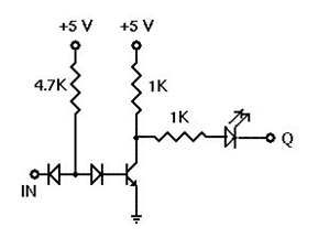
There is no switch in the original circuit, and this kind of logic does not work by opening and closing a switch.
Rather, the circuit works by bringing the voltage at the input pin "high", or bringing the voltage at the input pin "low".
When the switch is opened in your circuit, the input at D1 is "floating". In such a case, it will remain "high". The voltage from V2 will "pass through it".
[Or, more accurately, because there is no current through it, by Ohm's law, the voltage on each side will be the same. Now, you may say, "wait a minute, a diode is not a resistor, and no current flows through a diode when it is reverse biased". That is not quite true. A small "leakage current" does flow through a diode that is reverse biased, and a diode does behave like a resistor to the extent that, if there is really no current flowing through it, the voltage drop across it is 0.]
If you want to use a switch to provide an input for such circuits, use something like this:

simulate this circuit – Schematic created using CircuitLab
R1 is called a pull-up resistor, and R2 is called a pull-down resistor. The range of values that are acceptable depends upon the logic family that this circuit is supposed to be an input for. In this particular case, the values of the resistors can be 0. That is, you can omit them, and use wire instead. However, in practice, resistors are used to limit current and power consumption.


