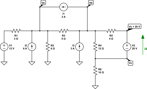
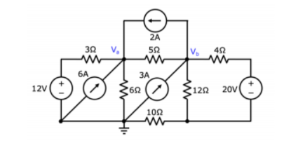
I have to find \$V_a\$ and \$V_b\$, when I tried to do so, using node analysis I had the Equation \$\frac{V_a}{6} + \frac{V_a-12}{3}+\frac{V_a-V_b}{5} - 6 - 2 = 0\$ and \$\frac{V_b}{22}+\frac{V_b-20}{4}+\frac{V_b-V_a}{5} +2-3=0\$. Solving it simultaneously, I got \$V_a = 23.29 \text{V}\$ and \$V_b=21.51 \text{V}\$. When I simulated it using Circuit simulator applet, the simulation says that \$V_a = 24.4 \text{V}\$ and \$V_b\$ is \$25.4 \text{V}\$. Can someone point out where did I go wrong? Thanks!
-
\$\begingroup\$ Is that a vb/22?? Should it be that? Also, your 20 V source is not based at ground. That has an impact. The unknown voltage at the bottom right matters, doesn't it? \$\endgroup\$– jonkCommented Mar 23, 2021 at 2:35
-
\$\begingroup\$ Those aren't really equations without an equal sign. Are they both set equal to 0? \$\endgroup\$– MattCommented Mar 23, 2021 at 2:36
-
\$\begingroup\$ @jonk assuming that's the case, how can I equate it? I cant seem to find an equation to find it, All i have is Vc/10 + Vc/12 +Vc - 20 = 0, which equates to 16.90 when looking at the simulation, its wrong. \$\endgroup\$– Omar WaltonCommented Mar 23, 2021 at 3:00
-
\$\begingroup\$ @matt yes it is set to 0, im sorry i forgot to add it, edited it now hopefully it makes sense. Thanks for pointing it out. \$\endgroup\$– Omar WaltonCommented Mar 23, 2021 at 3:00
-
\$\begingroup\$ @OmarWalton I'll help. Just give me a minute to write it out. \$\endgroup\$– jonkCommented Mar 23, 2021 at 3:00
3 Answers
There are several mistakes. But you still did pretty good. Let's look at the schematic:

simulate this circuit – Schematic created using CircuitLab
Now all of the important nodes have been labeled and a new unknown current identified.
Your first equation should be:
$$\begin{align*} \frac{V_a}{R_1}+\frac{V_a}{R_2}+\frac{V_a}{R_3}&=\frac{V_1}{R_1}+\frac{0\:\text{V}}{R_2}+\frac{V_b}{R_3}+I_1+I_2\\\\\therefore\\\\\frac{V_a-V_1}{R_1}+\frac{V_a-0\:\text{V}}{R_2}+\frac{V_a-V_b}{R_3}-I_1-I_2&=0\:\text{A} \end{align*}$$
And you got that one right! So there's no problem, yet.
Your second equation should be:
$$\begin{align*} \frac{V_b}{R_3}+\frac{V_b}{R_4}+\frac{V_b}{R_5}+I_1&=\frac{V_a}{R_3}+\frac{V_c}{R_4}+\frac{V_c+V_2}{R_5}+I_3\\\\\therefore\\\\\frac{V_b-V_a}{R_3}+\frac{V_b-V_c}{R_4}+\frac{V_b-V_c-V_2}{R_5}+I_1-I_3&=0\:\text{A} \end{align*}$$
Note that this is quite different from yours. One of the differences is that you used \$22\:\Omega\$ instead of \$R_4=12\:\Omega\$, I think. But actually there are more serious errors, as you can see. So this is really minor, by comparison.
You need two more equations. One of them is very simple:
$$\begin{align*} \frac{V_c+V_2}{R_5}&=\frac{V_b}{R_5}+I_4\\\\\therefore\\\\\frac{V_c+V_2-V_b}{R_5}-I_4&=0\:\text{A} \end{align*}$$
The final one is:
$$\begin{align*} \frac{V_c}{R_4}+\frac{V_c}{R_6}+I_4&=\frac{V_b}{R_4}+\frac{0\:\text{V}}{R_6}\\\\\therefore\\\\\frac{V_c-V_b}{R_4}+\frac{V_c-0\:\text{V}}{R_6}+I_4&=0\:\text{A} \end{align*}$$
That's it. From these four you can work out all of \$V_a\$, \$V_b\$, \$V_c\$, and \$I_4\$.
Took me less than 10 minutes to write this out.
-
1\$\begingroup\$ Wow. He said "where did I go wrong" and I said "22". You put in a lot more effort :). \$\endgroup\$– MattCommented Mar 23, 2021 at 4:10
-
\$\begingroup\$ @Matt I said that much in a comment, not an answer. I like answers to be a little more complete, is all. Thanks for the kind comment! \$\endgroup\$– jonkCommented Mar 23, 2021 at 4:16
The 22 seems wrong. There's a third node that I think you should account for, between the 10 and 12 ohm resistors.
Unless the assignment calls for using node analysis, you might find it easier to use successive Norton/Thevenin transformations. The Thevenin equivalent of V1, I2, R1, R2 is 20 volts in series with 2 ohms. The Thevenin equivalent of I1, R3 is 10 volts in series with 5 ohms. The Thevenin equivalent of V2, R4, R5, R6, I3 is 54 volts in series with 13 ohms. You can find all those without putting pencil to paper. Then the current flowing right to left, in the direction of Vb to Va is 54+10-20 volts over 13+5+2 ohms or 2.2 amperes. Va is 24.4 volts and Vb is 25.4 volts.
I don't have points enough to comment but you should know that I have never, in almost 60 years, had any need to use node-voltage or loop-current analysis. Were it not for this website, where I get puzzles requiring them, I never would.
My comment about not putting pencil to paper is only partly true. I might not have overlooked one of the current sources for my first answer if I had.

