I'm struggling to understand the purpose of the resistor circled in red, I know it has something to do with DC biasing and the feedback on the circuit (as the capacitor will cause AC bypass). But I'm struggling to understand the exact circumstance where this would be needed. Is it a change in supply voltage, or change in transistor beta? And the exact mechanism that would cause the resistor to solve the problem.
-
3\$\begingroup\$ Just a couple of words to look up "emitter degeneration". Whole books could be written on the subject. \$\endgroup\$– Lorenzo MarcantonioCommented Mar 29, 2021 at 12:56
-
\$\begingroup\$ Can I suggest changing the title to something like "Purpose of the emitter resistor". The fact that you have circled a component in your diagram is not really relevant to the title of the question, which people will see when browsing or searching. \$\endgroup\$– RodneyCommented Mar 29, 2021 at 17:56
6 Answers
I'm struggling to understand the exact circumstance where this would be needed.
What most folk want with a common emitter amplifier is for the DC collector voltage to be about half the supply voltage. So, when you have an AC signal present at the input, the amplifier's output (collector) doesn't clip the signal asymmetrically. Another way of phrasing it is that you are aiming for a good linear dynamic range capability.
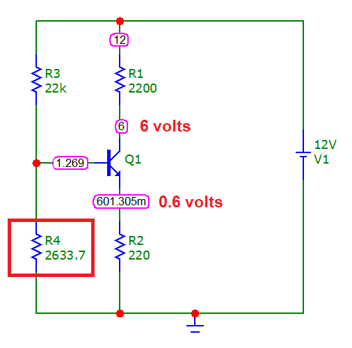
To achieve this, you need to create a situation where the DC quiescent collector current is held fairly constant. So, if Vcc is (say) 12 volts and Rc is (say) 2200 Ω then you want the quiescent current through Rc to be about 2.73 mA (2.73 mA through a 2k2 resistor drops 6.006 volts).
To ensure that a DC current of 2.73 mA flows through Rc consistently requires an emitter resistor. If the emitter resistor is 220 Ω (for example), a DC current of 2.73 mA flows from the collector into the emitter and then through the resistor and, it would drop about 0.601 volts across it.
It then follows that the base-bias voltage would need to be about 0.601 volts plus about 0.7 volts (internal base-emitter volt-drop). So, around 1.301 volts on the base will ensure that there is approximately 6 volts DC at the collector.
Knowing this allows you to calculate the base-bias resistor values. Here's a simulation where I've tweaked R4 to show what I mean: -
In this example I used a BC547 BJT and the base voltage to ground is 1.269 volts (implying that the base-emitter volt-drop is 0.669 volts). So, it's easy to follow and you should nearly always get predictable results but you'll never get exact results from a single BJT amplifier.
So, that's the normal case when an emitter resistor is used.
If you didn't have an emitter resistor, how can you properly define the current flowing in the emitter (and the collector)? Well, you can if you know the maths surrounding a CE configuration but, then you'll find that temperature effects will be surprisingly high and the desired 6 volts at the collector may drift with temperature a few volts this way and that way.
So, do you want a 5h1tty circuit that drifts around or, do you want a stable circuit?
But I'm struggling to understand the exact circumstance where this would be needed. Is it a change in supply voltage, or change in transistor beta?
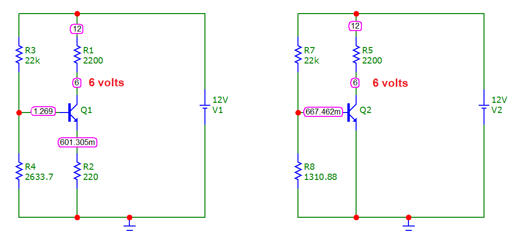
It's both and, it's also temperature and, it's also circuit repeatability. Here's a side by side comparison: -
And, if I increased R4 in the left circuit and R8 in the right circuit by 5% we would see this: -
Can you see that a very small change in the biasing condition hasn't really altered the quiescent DC voltage on the left-hand circuit but, on the right-hand circuit, the collector voltage has dropped from 6 volts to 188 mV. The right-hand circuit is very susceptible to component drift.
If I restore the resistor values and increase the power supply voltage from 12 volts to 13 volts here's what we see: -
In other words, the right-hand circuit is very susceptible to power voltage changes (and also component value changes). If I restore the supply voltage to 12 volts and change the ambient temperature in my simulation from 27°C to 37°C we see this change: -
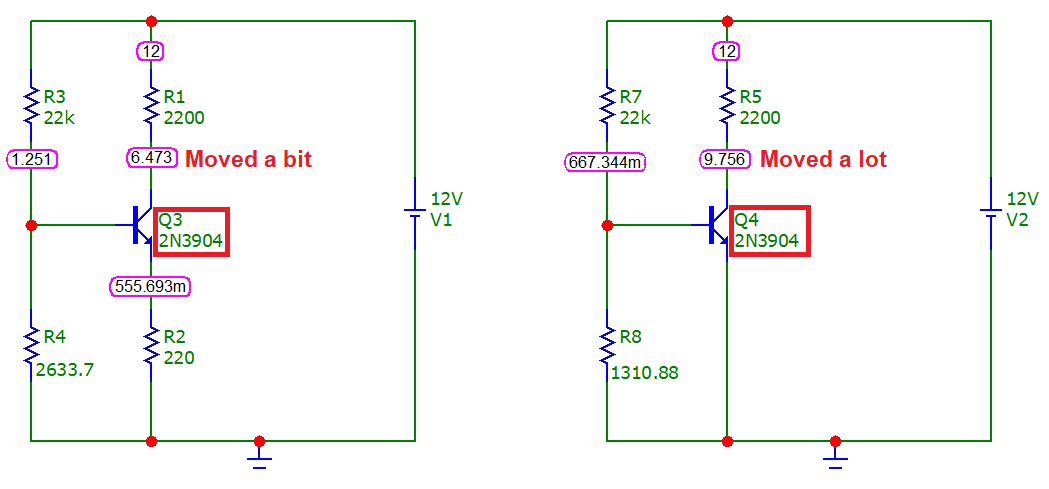
In other words, the right-hand circuit is very susceptible to power voltage changes, component value changes and ambient temperature changes. But, what if I swapped out the transistor with a 2N3904: -
The above has restored ambient back to 27°C but swapped the BC547s for 2N3904s. The circuit on the left is clearly more robust at dealing with this situation.
The emitter resistor serves mutiple purposes. It improves the linearity of the amplifier, raises the input impedance, and simplifies biasing. Let us look at each characteristic individually.
In the following I will refer to variation of the circuit with \$R_E\$ omitted as the 'grounded common-emitter amplifier'.
Linearity
The gain of the grounded common-emitter amplifier is \$G=-R_C/r_e=-R_CI_C/{25\mathrm{mV}}\$. Here, \$r_e\$ is the intrinsic emitter resistance, ie the reciprocal of the transconducance. If the input signal is large enough, it will substantially modulate the collector current \$I_C\$, and hence the gain. If the gain depends on input signal level, that is precisely a non-linearity!
The added emitter resistor changes the gain to \$G=-R_C/(r_e+R_E)\$. Clearly, the gain does not nearly depend as much on small changes in \$r_e\$ now.
Input impedance
The input impedance looking into the base of the grounded common-emitter amplifier is approximately \$Z_\mathrm{in} = \beta (r_e + R_E)\$. For \$I_C=1\mathrm{mA}\$, \$r_e\$ is just 25 Ohms. By making \$R_e\$ larger than this, the input impedance can be increased significantly. Remember that if the input signal is a voltage, a high input impendace is usually desirable.
Biasing
Say you trimmed the input bias divider such that just the right collector current flows through the transistor. For the grounded emitter variant, the biasing will not be stable. Any change in temperature will create a variation in the base-emitter voltage (at fixed \$I_C\$) of the transistor. Conversely, when we keep the actual \$V_\mathrm{BE}\$ constant, this creates an exponential change in the collector current. A change of just a few °C can saturate the output.
The situation is the same for variations in the power supply voltage. A change of as little as 25mV at the base will increase/decrease the quiescent current by a factor \$e\$.
Adding the emitter resistor gives some compliance to the emitter voltage, reducing this problem. If it is much larger than \$r_e\$, the perturbing voltage can drop across \$R_E\$, rather than actually changing \$I_C\$ too much.
Conclusion
Adding the emitter resistor greatly improves all these properties, at the expense of gain.
If you are still struggling with these concpets, have a look at chapter 2.3.4 of The Art of Electronics (3rd edition) by Horowitz & Hill. The single best reference on this topic around.
Note about the emitter capacitor
In the schematic in the OP there is a capacitor parallel to the emitter resistor. This way, \$R_E\$ is bypassed at signal frequencies. This yields the same high gain as for the grounded emitter amplifier (including the degraded linearity and input impedance), but sill offers reliable biasing.
-
\$\begingroup\$ What about the output impedance for those AC signals? Isn't lowered (not a rhetorical question)? \$\endgroup\$ Commented Mar 30, 2021 at 15:46
-
\$\begingroup\$ The output impedance is always equal to the collector resistor Rc. The collector itself looks like a current source, i.e. high imepdance, limited by the Early effect only. \$\endgroup\$– polwelCommented Mar 30, 2021 at 16:46
Look at the emitter circuit.
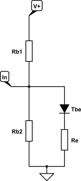
simulate this circuit – Schematic created using CircuitLab
As soon the base-emitter diode reaches its forward voltage, the bias runs away. You cannot completely solve this problem as you want to have current running into the base. But you don't want to have a diode characteristic at that place. You want it linear. That's what the emitter resistor does. It lineriarizes the current through the BE diode. Same as a series resistor does it for any other diode. The circuit is now more stable against fluctuations of V+.
-
1\$\begingroup\$ Interesting explanation... but one very important detail is missing in this conceptual circuit diagram - the collector current that flows through the emitter resistor Re and creates a "lifting voltage drop". So there is not only a resistor in series to the "diode" but a resistor supplied by a current, i.e , a "lifting" voltage source with Ve = Ic.Re. \$\endgroup\$ Commented Mar 28, 2021 at 21:34
RE is needed to cope with the power supply voltage fluctuation, and it keeps the operating point stable.
For small signals, it will reduce the gain so a capacitor bypasses it for small signals. In other modes you have the same considerations.
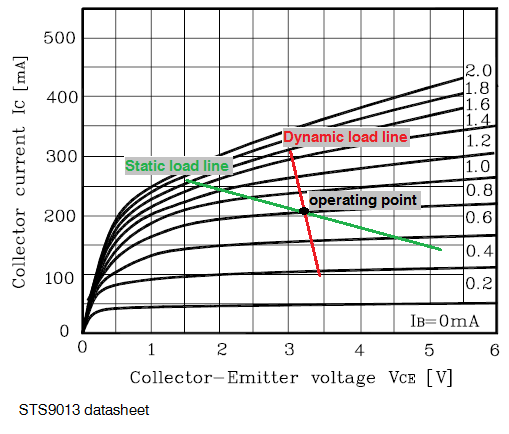
If you look at the static load line you will see that a variation of VCE does not result in a large variation of IC, so when the power supply fluctuates VCE changes, but the operating point does not move a lot.
-
1\$\begingroup\$ But that's where I don't understand how it is kept stable \$\endgroup\$ Commented Mar 28, 2021 at 9:55
-
\$\begingroup\$ I edited it to add more explanation. \$\endgroup\$ Commented Mar 28, 2021 at 10:10
-
\$\begingroup\$ @Paul, I can't agree with your last edit. When the power supply fluctuates, Vce follows its variations since the voltage drop across Rc is constant (because of the constant collector current). Re keeps stable only the collector current; it is not responsible for Vc. That is why this negative feedback is named "current-type". \$\endgroup\$ Commented Mar 28, 2021 at 22:17
-
2\$\begingroup\$ @circuitfantasist you are right and that is exactly what I wrote. "Does not result in a large variation of Ic" maybe you didn't read the "not". I wrote also that Vce changes. \$\endgroup\$ Commented Mar 29, 2021 at 1:32
-
And the exact mechanism that would cause the resistor to solve the problem?
The name of this mechanism is "negative feedback" (more precisely, "current-type negative feedback") and this specific transistor implementation is known as "emitter degeneration". As far as I can remember (not sure), one of the legends says that it ("cathode degeneration") was invented by Otto Schmitt in the 30s. Whoever invented this trick, it is an example of "ingenious simplicity" - only a resistor attached to the existing transistor stage.
Instead of repeating well-known explanations from the web, I will share with you a new insight of mine from yesterday. I had the inspiration to think about the great circuit in the case when Vcc varies.
My observations are that despite the presence of negative feedback, the circuit still responds to Vcc changes (for example, increase) because of two reasons:
1. The bias voltage VRb2 (Vb) increases because the voltage divider Rb1-Rb2 is directly supplied by Vcc (it acts as an input voltage attenuated by the divider and applied to the base). The transistor tries to make its emitter voltage equal to Vb; so the collector current Ic increases, the voltage drop VRc increases, and its complement - the collector voltage Vc, decreases. Figuratively speaking, the transistor "pulls down" the collector output.
2. We can think of Rc as some "battery" that "produces" the voltage VRc = Ic.Rc and it is connected in series to Vcc. So when Vcc increases, it "pulls up" the collector output through the "battery". This is the well-known "voltage shifting" technique widely used in op-amp internal structures.
My conclusion is that the two voltage changes are in opposite directions and can be mutually neutralized.
Indeed, it is not so important for this AC amplifier stage but there may be (DC) applications, in which it would be important. For example, such a "neutralized stage" can be considered as a voltage stabilizer ("Zener diode").
But above all, it is useful as a mental exercise for a deep understanding of the circuit operation.
-
\$\begingroup\$ We have subscript on this platform (
<sub></sub>) - poor man's MathJax. For example,V<sub>CC</sub>andR<sub>C</sub>. \$\endgroup\$ Commented Mar 30, 2021 at 15:52 -
\$\begingroup\$ @Peter Mortensen, Thanks for the reminder... and maybe, for the upvote... You are right, formatting should be used. I am meticulous myself and I refine my materials. But I just got tired already (I have been uploading materials to the web since 2000) and started saving some repetitive actions. In short, I focused more on the content than on the form. The truth is that I do not get an adequate response to what I offer, especially in this platform, and because of this reason I frequently lose desire... I think that some others here experience this too... \$\endgroup\$ Commented Mar 30, 2021 at 19:08
The quick answer. The NPN transistor switches on when the base voltage is about a diode drop above the emitter. So without that resistor to raise the emitter voltage it would be on all the time, or off all the time when the capacitor was charged.


