0
\$\begingroup\$

I have a simple circuit with uses a non-inverting op amp. Just for the shake of my learning, I want to add some noise to the op. amp.'s input and see if I can remove it applying filters.

To do this, I have a oscope which is able to generate a random signal (range -1V to +1V). In addition, I have the data of a a noise signal that has a +14V spike. Since the signal generator can only go to +1V, I will amplify this noise signal with another op. amp. to reach those +14V.

What I don't know is how to safely wire the circuit to superimpose my scope noise signal to the "production" op. amp. input (the op. amp. I want to test, not the one used to amplify the noise signal). I'm specially concerned about keeping safe my oscope.

How can I do this?

\$\endgroup\$

2 Answers 2

2
\$\begingroup\$

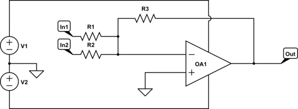
The following circuit is an inverting op-amp summation amplifier. Plug the two signals you want to combine into the In1 and In2 inputs. The grounding of the non-inverting (+) input to the op-amp, and the feedback configuration ensures that the inverting (-) input to the op-amp is virtually at ground, so that the two inputs should not affect one another in any noticeable way -- only the output of the op-amp will have a combined signal.

schematic

simulate this circuit – Schematic created using CircuitLab

\$\endgroup\$
2
  • \$\begingroup\$ Will this work the same way for a non inverting amplifier? \$\endgroup\$
    – Martel
    Commented Apr 4, 2021 at 12:05
  • \$\begingroup\$ In a non-inverting configuration, the two inputs are not "virtually" isolated. You may want to buffer the inputs (as per @Abel 's answer) to isolate them from each other. If the input resistors are large enough, you may not care about cross-talk between the inputs, but since you are trying to measure noise/distortion, you need to check how much effect such cross-talk will have on your measurements before assuming it is negligible. \$\endgroup\$ Commented Apr 4, 2021 at 15:13
1
\$\begingroup\$

I'd use several additional op amps, resistors. Naturally the Op amps will need supply power. Being lazy, I'll refer to other posts' circuit diagrams that contain what I'm talking about for now.

One op amp would be in a buffer configuration Buffer op amp amplifier saturation (no resistors, just copies a voltage) to protect the oscilloscope. You may also want to protect the original signal in a similar way depending on how sensitive it is and whether stressing it is part of your test. That covers the upstream sources. Instead of using the protected source, you use the output of the buffer op amp. The buffer essentially copies it but powers it from the op amp's supply.

Next comes the op amps for a downstream super-imposed signal. This can be achieved by an amp in the summing configuration Is there a limit to the number of inputs that can be summed with an op-amp summing circuit? There's some annoyance if you don't want to negate the sum so you might prefer to do a subtraction operation instead. Subtracting two voltages using an op-amp

With that, you'll have a downstream superimposed signal and you won't draw power from the upstream sources that you chose to buffer and protect. You will however want to run numbers for your power supply - the worst cases for current running through all the resistors you used and the downstream signal. If it's too much, you will likely need to increase resistance values on that addition/subtraction amp, keeping in mind that error on a resistor is usually a % of its value.

\$\endgroup\$

Your Answer

By clicking “Post Your Answer”, you agree to our terms of service and acknowledge you have read our privacy policy.

Not the answer you're looking for? Browse other questions tagged or ask your own question.