3
\$\begingroup\$

I'm building a LED driver using Diodes AL8871Q IC to power a XHP70 LED powered from a 4 series protected Lithium battery pack, integrated on the board it has an Attiny85.

I plan to use the Attiny85 to control the PWM pin on the AL8871Q, read voltage from an NTC thermistor. I am using a Diodes AP7370 SOT23 regulator to power the Attiny85 from the incoming 14v VIN.

Using a bench top power supply to emulate a battery pack, I set to 14V 1A and hook everything up including LED load. Powering on the PSU, all works, I can control the PWM of the Attiny85 which in turns control LED brightness.

Problem I have is when I tried with a battery the LDO regulator burns out. So I tried with a new LDO regulator, turning on the PSU before connecting to my circuit, it burns the LDO regulator.

I figured that the PSU has a soft start that stops the in rush of current vs battery or connect an already on PSU.

Is this what is happening? How can I prevent it from happening with adding the least amount of components.

Scenerios

PSU set to 14v 10A

  1. Works Circuit is connected to powered down PSU, LED/load is connected. Power on PSU, Attiny boots up fine, triggers PWM that controls AL8871Q IC that powers the LED. All this happens almost instantaneously. Scopes shows PWM duty cycle at 40% as programmed on Attiny85. PSU displays shows 25W power drawn, voltage reads 14v and 1.8A+-.

  2. Burns PSU powered on NOT connected to circuit. LED is connected to circuit. PSU is then connected to circuit. AP7370 burns up and breaks.

  3. Burns 14.8V battery pack is connect to circuit, AP7370 burns up

  4. Works Circuit is connected to powered down PSU, NO LED/load connected. Power on PSU, Attiny boots up. Scopes shows PWM.

  5. Works Attiny85 & AP7370 removed from circuit, PSU powered ON then connected to circuit with LED connected. PSU displays shows 50W power drawn, voltage displays 6+V and about 8+A.

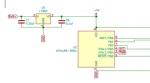
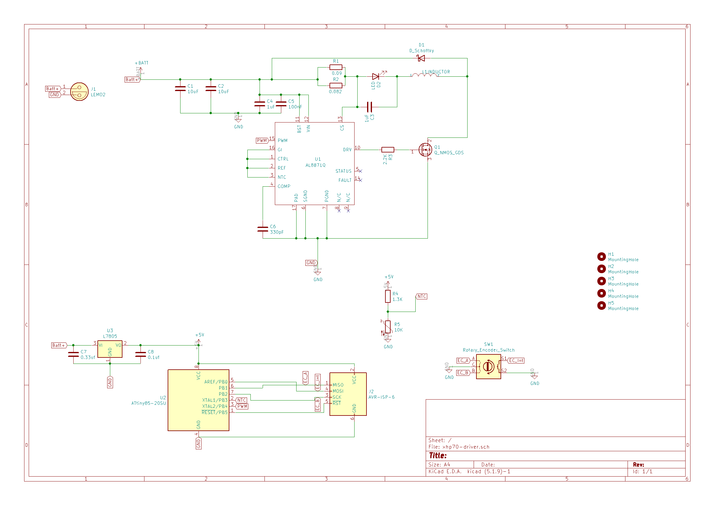
Schematic has 7805 labelled wrongly, it should be AP7370 Portion of schematic regarding the Attiny85 and 7805

Full Schematic

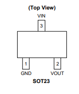
LDO Pin out from Datasheet

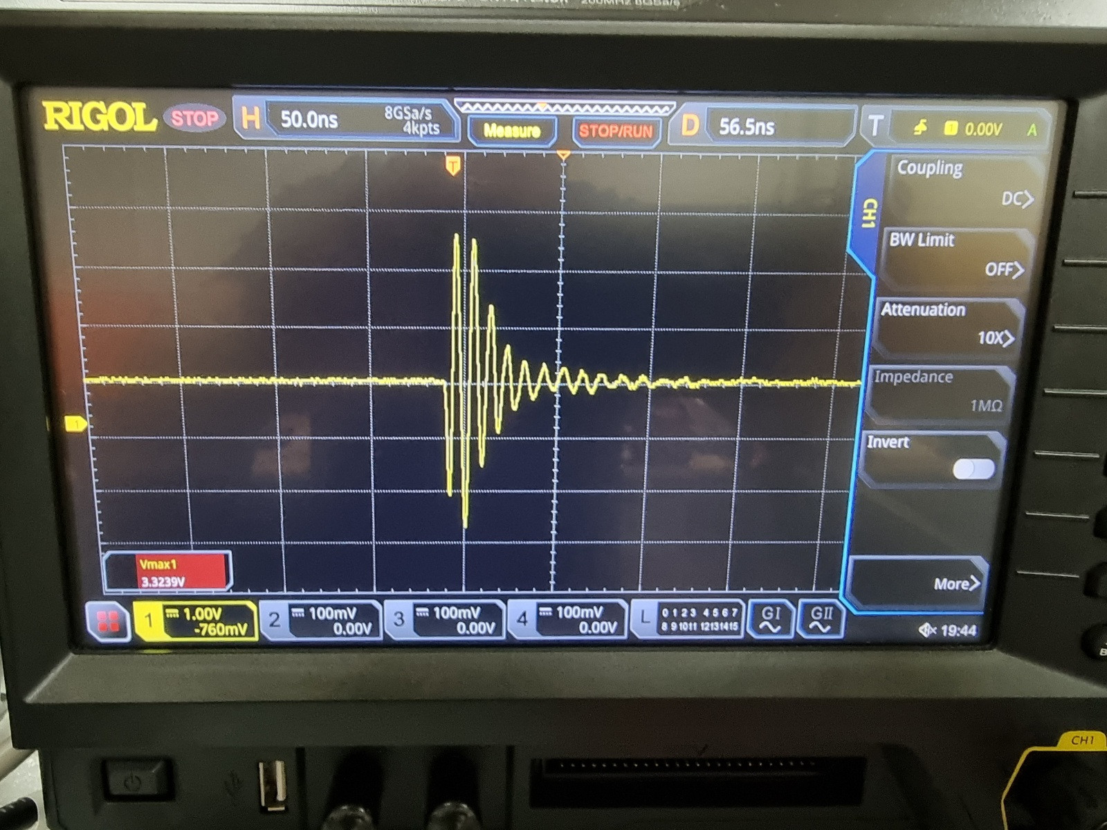
Photo of scope when connecting to a 11.1v
Battery with LED connected.

\$\endgroup\$
13
  • \$\begingroup\$ Can you show us the rest of the circuit with regard to the power rails, please? A block diagram should be sufficient. \$\endgroup\$ Commented Apr 15, 2021 at 13:46
  • 1
    \$\begingroup\$ It is very probably overheating due to excessive power dissipation. Lower the input voltage (and it still might not like 1A). Alternatively, use a buck (switch mode) converter. \$\endgroup\$ Commented Apr 15, 2021 at 13:47
  • \$\begingroup\$ According to the datasheet, this device has a thermal shutdown function. Did you allow the device to cool down after it "burned"? \$\endgroup\$
    – Bart
    Commented Apr 15, 2021 at 13:49
  • \$\begingroup\$ @intosite: The 7805 is a linear regulator, but not a low drop out regulator. Low drop out refers to linear regulators that can operate with a very small difference between the input voltage and the regulated output voltage. LDO regulators are linear regulators, but not all linear regulators are LDO regulators. The 7805 has a minimum drop out of 2V. You have to give it at least 7V in order to get 5V out. \$\endgroup\$
    – JRE
    Commented Apr 15, 2021 at 14:15
  • 1
    \$\begingroup\$ @intosite Do you definitely have the input to the AL8871Q subsystem connected to the Batt + node and not the +5V node? If it's something you can take a well-exposed, high-res photo of, you could edit your question to add that - some people here are excellent at spotting wiring mistakes. \$\endgroup\$ Commented Apr 15, 2021 at 18:14

6 Answers 6

6
\$\begingroup\$

If the LED is drawing its power through the 7805, the regulator will require a large heatsink. If the bench supply has an adjustable current limit restricting the output to a max of 1 A, this might be why the regulator survives bench operation. A lithium battery has no such limiting.

BTW, the 7805 is not a low-dropout regulator. It is a second-generation single-chip regulator from the 60's/early 70's, and needs over two volts differential between its input and output to work properly.

\$\endgroup\$
5
  • \$\begingroup\$ +1 alone for " the 7805 is not a low-dropout regulator." The rest is good, too. \$\endgroup\$
    – JRE
    Commented Apr 15, 2021 at 14:12
  • \$\begingroup\$ I don't think the LED is drawing power through the LDO. Cause if I turn on the PSU with everything connected, the LED runs for few minutes and everything works. It only burns out when I turn on the PSU before connecting it to my circuit. Also even with the PSU set to 14V 15A output, it runs fine, though it reports power drawn only at about 25W. \$\endgroup\$
    – intosite
    Commented Apr 15, 2021 at 14:27
  • \$\begingroup\$ FWIW, no matter how old it is, a 7805 would do the job here just fine. There's no need for an LDO when dropping from 14V all the way down to 5V. \$\endgroup\$
    – TooTea
    Commented Apr 16, 2021 at 9:03
  • \$\begingroup\$ I know, but the TS might not. I have encountered this before, the incorrect idea that all 3-terminal regulators are LDO's. Buzz-word creep. And as my posting history shows, I have zero problem with old parts in new jobs. \$\endgroup\$
    – AnalogKid
    Commented Apr 16, 2021 at 12:15
  • \$\begingroup\$ @tootea I actually wanted a 7805, but somehow when selecting the component selected the LDO, not knowing better. And as such did up a pcb with LDO pin outs instead of a 7805... \$\endgroup\$
    – intosite
    Commented Apr 20, 2021 at 14:59
3
\$\begingroup\$

There is only 100nF capacitor at the output of the LDO, so perhaps it is oscillating. This should not result in its destruction, but who knows.

The datasheet isn't very helpful as it contains no advice on capacitor selection, which is a red flag, but all the examples use a 1µF cap on the output, so perhaps replacing the 100nF cap with 1µF could help.

\$\endgroup\$
3
  • \$\begingroup\$ Sorry which are you referring to? The LDO in my schematic does not have any 100nF capacitors connected to it. \$\endgroup\$
    – intosite
    Commented Apr 15, 2021 at 16:25
  • \$\begingroup\$ @intosite: "100nF" = 0.1µF. \$\endgroup\$
    – JRE
    Commented Apr 15, 2021 at 16:35
  • \$\begingroup\$ Oh , ok will try that. \$\endgroup\$
    – intosite
    Commented Apr 15, 2021 at 16:41
3
\$\begingroup\$

You have an oscilloscope as mentioned in the comments.

  1. Check the battery voltage - most likely higher than 14V by a good bit.
  2. Hook up your AL8871Q with the LED to the battery, but with the AP7370 and the processor removed.
  3. Check the battery voltage with the oscilloscope while the LED is lit.

I think you will find that there are peaks on the battery voltage going up to more than 20V. This will be caused by the switching action on the inductor. It won't take much of that to kill the AP7370.

Verify that as the cause of the failure. If that's the cause, then the solution is to keep the peaks away from the regulator.

That could be as simple as a resistor with a Zener diode or a resistor with a capacitor filtering the power to the regulator.

\$\endgroup\$
3
  • \$\begingroup\$ Ok will do. Actually I just remembered that the battery I used was only 13V, it was a 4S Lithium Iron Phosphate back (intended final pack will be Lithium Ion pack at 14.8V). The same thing happens when connecting an already powered on bench PSU. Can I do the same test using the PSU? \$\endgroup\$
    – intosite
    Commented Apr 15, 2021 at 16:44
  • \$\begingroup\$ If you do it with the PSU, then turn the current limit up. 1A is probably too low for the spikes to really kill the AP7370. \$\endgroup\$
    – JRE
    Commented Apr 15, 2021 at 16:49
  • \$\begingroup\$ Noted! Will do the test without the AP7370 and MCU first. Killed way too many AP7370 :( \$\endgroup\$
    – intosite
    Commented Apr 15, 2021 at 16:50
1
\$\begingroup\$

The destruction of the regulator may be caused by a transient overvoltage you get when you connect your circuit to either the battery or the PSU. I think the story is the following:

  1. when you connect the circuit, there is a large inrush current in capacitors C1 and C2
  2. because of the stray inductance between the voltage source (battery or PSU) and the capacitor, a resonance appears, and capacitors C1 and C2 can be charged at a voltage clearly above 14V. If there where no losses (resistance), the voltage could reach twice the voltage of the battery or PSU, that is 28V
  3. this voltage exceeds the maximum input voltage of the regulator (20V) and the device fails.

In order to test this hypothesis, you can connect a scope at the input of the circuit, in parallel to C1. You don't even have to put a new regulator. Then configure the oscilloscope in mode "single", and connect the voltage source. You should obtain the voltage at the entrance of your circuit. If it exceeds 20V, you have the explanation.

To avoid this phenomenon, you can:

  1. put a resistor in series with the circuit, and a relay in parallel with the resistor. The resistor limits the inrush current, and then the voltage peak
  2. the relay must driven by your arduino. It has to be closed after a delay sufficient for the capacitors to be charged
  3. only after the relay is closed (which short circuits the resistor) you can start the PWM

You don't kill the regulator when you power the PSU, while it is already connected, because the voltage increases more slowly.

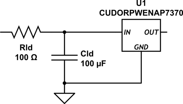
[EDIT] Actually there in a simplier solution, because the only component which is at risk is the regulator: only put a resistor in series with the input of the regulator, and you don't even have to add a relay, given the small current that will flow.

schematic

simulate this circuit – Schematic created using CircuitLab

The actual values of Rld and Cld can be adjusted to avoid a large voltage drop across Rld (depends on the current drawn be the arduino) and to provide a time constant Rld*Cld large enough compared to the voltage transient across C1

\$\endgroup\$
7
  • \$\begingroup\$ That sounds great, as I have limited estate space left. What would be a good size resistor to use? Is 0805 sufficient? \$\endgroup\$
    – intosite
    Commented Apr 16, 2021 at 0:19
  • \$\begingroup\$ @intosite : it should be ok for the voltage. For the power rating, it depends no the current the MCU sinks. It should be ok if it is less than 30mA. \$\endgroup\$ Commented Apr 16, 2021 at 12:21
  • \$\begingroup\$ The mcu datasheet says max 200mA. I would like to cater for that if possible. \$\endgroup\$
    – intosite
    Commented Apr 16, 2021 at 14:46
  • \$\begingroup\$ @intosite: 200mA is the maximum allowed current. The actual current is equal to the internal consumption (see Figure 22-2 on the datasheet) + peripherals (Table 22-1 : less than 2mA) + the current sourced by the MCU to power external circuits. Not much with your schematics. My advice: try with 100Ohms, measure the voltage drop accross Rld. It should not exceed 5V. \$\endgroup\$ Commented Apr 16, 2021 at 15:26
  • \$\begingroup\$ Just had access to the scope. Took a photo of the reading parallel to C1. Not sure but seems like the voltage spike is about 5v peak to peak. \$\endgroup\$
    – intosite
    Commented Apr 19, 2021 at 13:19
0
\$\begingroup\$

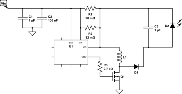
The current sense and output circuit should be like this. This is why the inductor is causing a reverse spike in the circuit when the input voltage sags below the MOSFET output, causing the fault. :

schematic

simulate this circuit – Schematic created using CircuitLab

\$\endgroup\$
0
\$\begingroup\$

1 - You are applying about 15 volts and drawing 1.8 amps.

2 - Your regulator output is 5 volts. That means that the regulator is dropping 10 volts across it.

3 - Since the device is passing 1.8 amps, it is dissipating 1.8 x 10, or 18 watts.

4 - You are using an SOT23. From the data sheet, P 2, the maximum thermal resistance from chip to ambient is 203 deg C/watt. If the chip could handle the situation, the interior temperature of the IC would be (203 x 18), or 3,654 degrees. Since ambient will be somewhere around 20 degrees C, the expected chip temperature is expected to be something like 3,674 degrees C. Do you see why it is failing? And let me guess - it's failing instantly upon connection. Do you understand why?

5 - You need a much beefier regulator/heatsink combination. Assuming you're willing to live with a 50 degree C rise, or a final chip temperature of 70 to 80 degrees C, you'll need a heatsink with a thermal resistance of no more than about 2.5 degrees/watt.

Here is the data sheet for a suitable heatsink, the Ohmite BGA425-125E, although it's intended to be clamped to a BGA IC, so mounting could be a problem. It's 42 mm square, and about 1/2 in high.

Perhaps more usefully, this sort of situation cries out for a switching regulator rather than a linear.

\$\endgroup\$
2
  • \$\begingroup\$ Regarding point 4, I can run my circuit for 60 mins (while keeping LED and MOSFET cool), AP7370 is cool to the touch without any heat sinking, all these only when using the PSU connected then powering up. \$\endgroup\$
    – intosite
    Commented Apr 16, 2021 at 2:02
  • \$\begingroup\$ @whatroughbeast: The 5V regulator is only supplying current to a microprocessor. The high current only goes through the AL8871Q LED driver and the LED. \$\endgroup\$
    – JRE
    Commented Apr 16, 2021 at 13:09

Your Answer

By clicking “Post Your Answer”, you agree to our terms of service and acknowledge you have read our privacy policy.

Not the answer you're looking for? Browse other questions tagged or ask your own question.