2
\$\begingroup\$

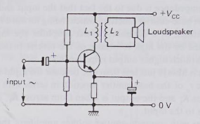
I have seen that the following circuit is mentioned as a single-ended class A power amplifier.

enter image description here

Also, push-pull configuration is mentioned as a better power amplifier, which isn't single-ended, and has two transistors in emitter follower configuration.

Can't we use only a single transistor in emitter follower configuration to have a single-ended class A power amplifier, driven by previous small-signal amplifier stages? The input impedance of emitter follower is almost \$\beta \$ times the impedance of its load. So a transformer may not be needed for impedance matching as used in the circuit shown above.

\$\endgroup\$
1

3 Answers 3

6
\$\begingroup\$

Can't we use only a single transistor in emitter follower configuration to have a single-ended class A power amplifier

Sure we can, I guess you mean something like this:
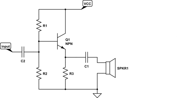
schematic

simulate this circuit – Schematic created using CircuitLab

Now imagine that I want a certain output power, that means a certain current needs to be delivered to the speaker. The speaker needs AC, there cannot be a DC current flowing through the speaker so that's why C1 blocks the DC.

Now imagine we need a signal of up to 100 mA to the speaker. That signal needs to be positive and negative. That's from -100 mA to + 100 mA so a total range of 200 mA.

The current through Q1 can only be positive so the solution with the lowest current consumption is to make the current through Q1 vary between 0 and 200 mA. When there is no input signal, 100 mA flows through Q1 and R3. That is what we call quiescent current or biasing current. This current flows even when you turn the volume all the way down! Imagine what this would in a battery powered device. Sure we can lower that current but then the maximum volume would be limited as well.

This high quiescent current consumption is the result of choosing a class A stage. A class-A push pull stage would have the same quiescent power consumption.

The advantage of using a transformer like in the circuit that you show is that you can trade voltage and current. Suppose the speaker still needs 100 mA but I'm using a 10:1 (primary:secondary) transformer. Then at the primary side the current will be 10x lower! OK, the disadvantage is that I will need a voltage that is 10x higher. But with low ohmic speakers (8 Ohm etc) that is not an issue, at 100 mA that would result in 0.8 V. Multiply that by 10 and we get 8 V which is a reasonable output voltage for a supply of 12 V.

So in summary: yes we can use an emitter follower and indeed it does have a low output impedance. However what you didn't think about is that although the small signal impedance of an emitter follower is quite low (1/gm) that does not mean it can deliver enough current to drive a low impedance load like a speaker directly. That's why a transformer is a good idea, it transforms the low impedance of the speaker into a higher impedance that is easier to handle for a low power circuit.

\$\endgroup\$
6
  • \$\begingroup\$ Thanks. As you know maximum power is transferred to the speaker if the impedance of the speaker equals the output impedance of the amplifier. At the moment, I don't know why the circuit with a transformer is better at this than the emitter-follower circuit you draw, if it is at all. \$\endgroup\$
    – apadana
    Commented Jul 21, 2021 at 11:49
  • \$\begingroup\$ As you know maximum power is transferred to the speaker if the impedance of the speaker equals the output impedance of the amplifier. Sure that's a common misunderstanding, it is true but only in the case that you want to do impedance matching. Go ahead and design an emitter follower with an 8 ohm output impedance and see what quiescent current you get. How much current can your amplifier then drive? So what will be its maximum output power? \$\endgroup\$ Commented Jul 21, 2021 at 11:53
  • \$\begingroup\$ In the mean time I will design a low output impedance amplifier, have the impedances mismatch on purpose so my amplifier can output much more power than yours into 8 ohms. My point: it is not always true that impedance matching gives you the highest output power. Most efficient yes, highest power: no \$\endgroup\$ Commented Jul 21, 2021 at 11:55
  • \$\begingroup\$ I don't care what you can do or not. I'm looking for reasons, arguments. Is the circuit shown in the question a better class A amplifier than the circuit shown in your answer? Why? \$\endgroup\$
    – apadana
    Commented Jul 21, 2021 at 12:05
  • \$\begingroup\$ I don't care what you can do or not. The arguments are in my comments above. If you would just care to do the calculations I suggested (8 ohm output impedance, what quiescent current is needed?) then you would understand the reasons. But obviously you know better already so my help ends now. \$\endgroup\$ Commented Jul 21, 2021 at 12:12
1
\$\begingroup\$

A class-A amplifier is a heater with a very high continuous current. Most amplifiers are class-AB or lately class-D for much higher efficiency. An audio amplifier has an extremely low output impedance (0.04 ohms or less) that damps speaker resonances. If you match impedances then the speaker sounds like a bongo drum.

\$\endgroup\$
1
\$\begingroup\$

Maximum power transfer is obtained by matching the load impedance to a set source impedance. If you can vary the source impedance then maximum power transfer is achieved by reducing the source impedance to zero ohms.

At maximum power transfer when the impedance of the load has been adjusted to equal the impedance of the source, the efficiency is 50%. To increase the efficiency, either reduce the source impedance or increase the load impedance from their matched values.

\$\endgroup\$

Your Answer

By clicking “Post Your Answer”, you agree to our terms of service and acknowledge you have read our privacy policy.

Not the answer you're looking for? Browse other questions tagged or ask your own question.