10
\$\begingroup\$

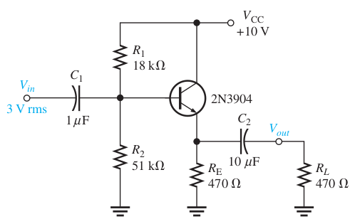
I tried to simulate an example common collector amplifier given in the book Electronic Devices by Floyd.

The circuit depicted in the book is:

enter image description here

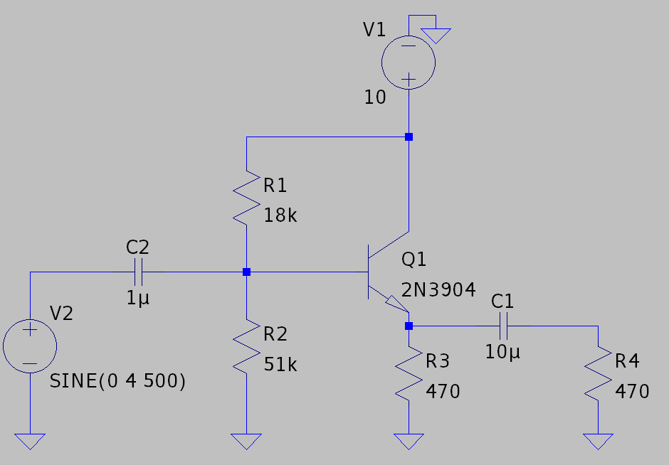
I used LTspice with transient analysis to implement and simulate the circuit:

enter image description here

Just after checking the input and output waveforms, I discovered the circuit has several problems. First, the output voltage signal gets clipped (or whatever the right term is) on the bottom part:

Green wave is the input (probed just after the sinusoidal input source). Blue wave is the output (probed just before the R4)

Green wave is the input (probed just after the sinusoidal input source). Blue wave is the output (probed just before R4.)

Second, there is some kind of "weirdness" in the input current:

enter image description here

On the other hand, if I decrease the input voltage to 3VP, those problems disappear, namely, I get a good output voltage and no irregularities in the input current.

What is the problem with this circuit?

  • For the input signal of 4VP, should not 10 VCC be enough for the amplifier?
  • How can I design a CC amplifier circuit that has a better output swing?
  • What is the problem with the input current?
  • Should not the current, in any case, be sinusoidal?
  • How does it get this "weird" shape?

I believe these questions are interrelated, so decided to ask them in just one post.

I am also pretty new to electronics and analog circuit design, so maybe there is something important I missed in the analysis of transistor amplifier circuits.

\$\endgroup\$
0

1 Answer 1

14
\$\begingroup\$

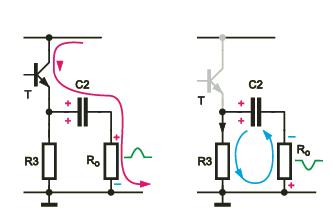
The problem is that the NPN transistor can only "source" the current and cannot "sink" current (current can only flow out of the emitter and never flow into emitter). In your circuit, \$R_E\$ resistor can only "sink" current.

Thus, the positive swing current is "provided" by BJT. But for the negative swing, we have a problem because now \$R_E\$ resistor needs to be able to "sink" this negative current.

What this schematic is trying to show in a simplified manner:
enter image description here

Negative clipping occurs when \$I_E \$ current reches \$I_E = 0A\$ (transistor is cutt-off).

Thus, the maxumum negative voltage you can get at the outpus is equal to:

\$V_{OUT_{MAX}} = V_{C_2} \times \frac{R_L}{R_E + R_L} = I_{EQ} \times R_L||R_E\$

Where:

\$V_{C_2}\$ is a DC voltage across output capacitor (DC voltage at the Emitter)

\$I_{EQ}\$ - Emitter quiescent current.

Why does the emitter follower clip?

How can I design a CC amplifier circuit that has a better output swing?

You can reduce the \$R_E\$ resistor value or use a push-pull emitter follower.

How does this Push-Pull amplifier work?

How does it get this "weird" shape?

In your circuit, the DC voltage at the base will be around \$V_B \approx 7V\$.

Thus, for the positive swing, the voltage at the base will be: \$V_{B_{DC}} + V_{IN} \approx 7V + 4V \approx 11V\$ at the peak of the input signal amplitude.

And this means the transistor will enter the saturation region because of \$ V_B > V_C + 0.5V\$. And in saturation, the base-collector is in forward conduction.

And this is why you see this "weird" shape.

\$\endgroup\$
5
  • 1
    \$\begingroup\$ What a wonderful answer! Nice. +1 \$\endgroup\$
    – jonk
    Commented Apr 17, 2021 at 17:58
  • 1
    \$\begingroup\$ @jonk Thanks for a nice comment. \$\endgroup\$
    – G36
    Commented Apr 17, 2021 at 18:12
  • \$\begingroup\$ Thank you for detailed answer! Just wanted to ascertain one point: you wrote that "... for the positive swing, the voltage at the base will be large than equal to ...". Should not it be "... less than or equal to ..." ? \$\endgroup\$
    – Fuad Zadeh
    Commented Apr 17, 2021 at 18:14
  • 1
    \$\begingroup\$ @FuadZadeh at the peak of the input signal amplitude. Try to analyze this example:electronics.stackexchange.com/questions/310471/… by starting from "In real amp life the situation will look like this: " \$\endgroup\$
    – G36
    Commented Apr 17, 2021 at 18:21
  • 2
    \$\begingroup\$ @R36 provided a very good answer, however when specifically answering the question "How can I design a CC amplifier circuit that has a better output swing?" he left out the most obvious answer: provide a larger supply voltage to avoid clipping. \$\endgroup\$
    – Supa Nova
    Commented Apr 17, 2021 at 19:32

Your Answer

By clicking “Post Your Answer”, you agree to our terms of service and acknowledge you have read our privacy policy.

Not the answer you're looking for? Browse other questions tagged or ask your own question.