3
\$\begingroup\$

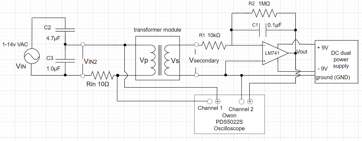
I am trying to find out the hysteresis curve of a transformer iron core. I use an LM741 for the op-amp integrator.

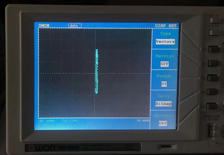
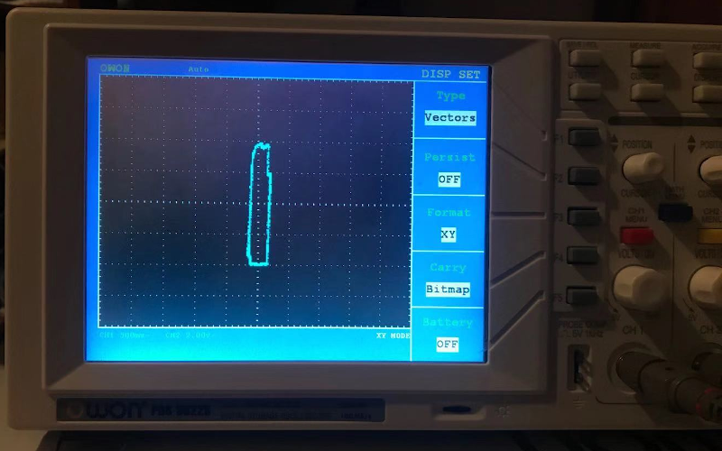
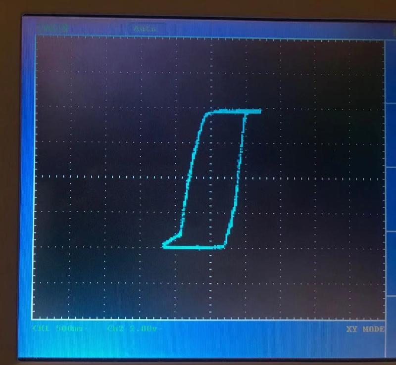
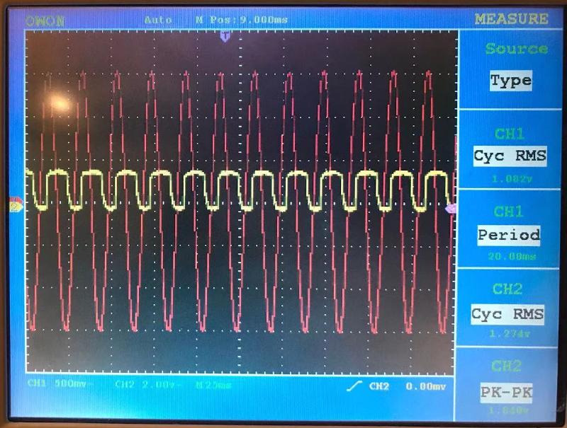
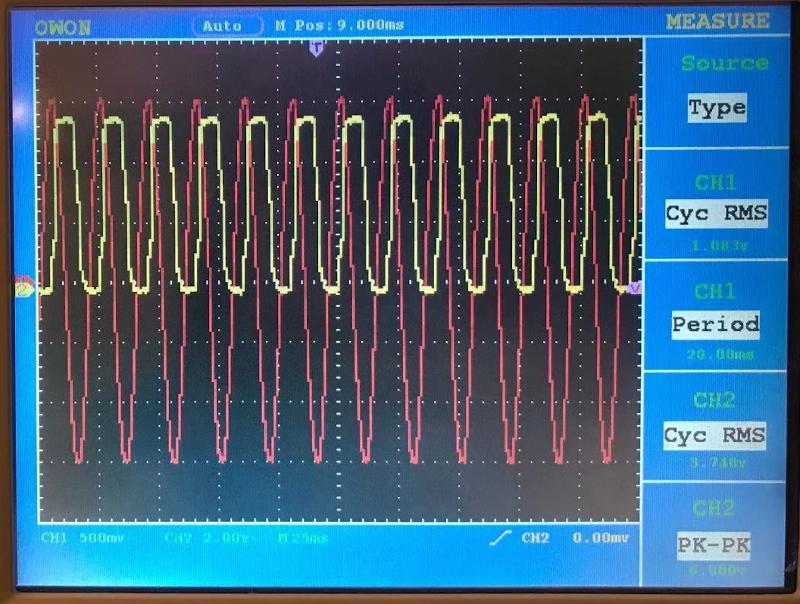
As I increase my 50Hz input voltage, I observe that Vin (value on the x-axis) does increase, while Vout (on the y-axis) increases very little. This does look like it is getting saturated, but I haven't seen the "linear region" on a B-H curve.

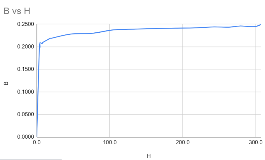
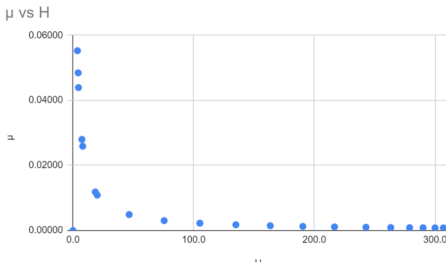
To find out why, I measured some data points, calculated B, H, and permeability with my other data, and plotted B vs H and permeability vs H. The left part of the graph is different from what it theoretically should be.

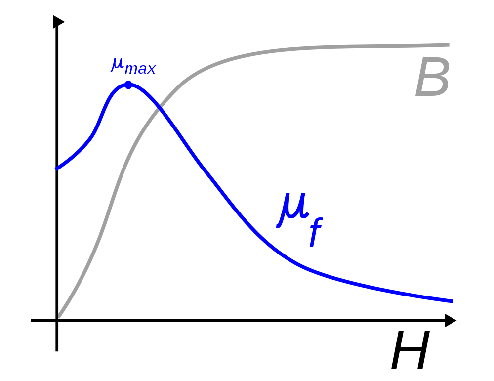
Theoretically, there should be a curve at the beginning(shown in the 3rd picture), which contains a section with a linear B-H relationship, but my B values are already so high at the very beginning.

I suspect that it's because Vout value also reflects the +-9v DC supply voltage for the opamp. I suspect this, because as I increased the DC supply, Vout increased too, which increased the height of the hysteresis curve.(just for testing, The DC supply was constantly +-9v in other times)

This makes the y-axis value already pretty high when my input voltage was only 0.02116v. Every time as I only increase a little Vin, this causes little Vout change. Thus, negligible changes on the y-axis are observed.

The iron core can't saturate already at 0.02116v, right? It approaches saturation so fast that it seems wrong. My measured permeability doesn't have a trend line at the beginning that leads up to its maximum point.

Am I just thinking too much or is something wrong?

1

2

3

enter image description here

enter image description here

enter image description here

enter image description here

enter image description here

9

\$\endgroup\$
19
  • \$\begingroup\$ magnetic materials can be made to saturate very fast ( have very high permeability). Whether this is the case for your core is a little unclear to me? what do you mean with 0.02 V ? Volt is not a unit related to core saturation..What is the magnetic field (in Oe or A/m) that you apply ? A schematic instead of your last image would greatly help with understanding. \$\endgroup\$
    – tobalt
    Commented Aug 5, 2021 at 15:54
  • \$\begingroup\$ When you run out of magnetic domains to flip, you simply run out. Then it's no different than an air core. \$\endgroup\$
    – jonk
    Commented Aug 5, 2021 at 15:55
  • 1
    \$\begingroup\$ @tobalt I replaced the last image with a schematic \$\endgroup\$
    – Juye C
    Commented Aug 5, 2021 at 15:57
  • \$\begingroup\$ @tobalt with 0.02V I meant what is measured by the oscilloscope's channel 1. It measures the AC voltage input that I fed in. I used it to measure the field strength H through ampere's law, H=NI/L. Thus the H is 3.7A/m. Is this a reasonable number at which a core could saturate? \$\endgroup\$
    – Juye C
    Commented Aug 5, 2021 at 15:59
  • \$\begingroup\$ that is far less than earths magnetic field. So: no. I suppose that you calculated it maybe wrong ? L would be the coil radius approximately \$\endgroup\$
    – tobalt
    Commented Aug 5, 2021 at 16:06

1 Answer 1

1
\$\begingroup\$

I have a couple suggestions here. I would measure both V and I on the same side of the transformer. B=uH.

Measure B=Integral(Vprimarydt)/(NturnsAcore)

Measure H=Nturns*Iprimary/Lcore. Measuring Iprimary could be done with a current probe or a shunt resistor. Make sure you don’t accidently short out your shunt through the scope chassis.

Use your scope to divide B/H to get u or plot them both in XY mode. Nturns, Acore, and Lcore are all constants. You may also have correct for gains of your current probe and voltage integrator but these are constants too assuming a fixed test frequency.

Also, the 741 isn’t very suitable as an integrator due to its relatively large voltage offset and input bias currents. Even with no input signal, these dc offsets will cause the 0.1uF capacitor to quickly integrate into saturation. Ex 80nA = I input bias = C dV/dt = 0.1uF dV/dt => dV/dt = 800mV/sec. This could be mitigated somewhat by using a bigger capacitor. I would also add a switch to short the capacitor through a 100 ohm resistor to reset the integrator to 0V. A more precise op amp would help a lot.

\$\endgroup\$
11
  • 1
    \$\begingroup\$ The integrator must be reset because the op amp is not ideal. It has DC offsets in both input current and voltage that will get integrated by the capacitor and cause the integrator output to drift. If the dc offsets are small and the capacitor is big, the drift might be slow enough that you can ignore it. Just push the reset switch at the beginning of your test. If you're interested in how to reduce amplifier dc errors, look up chopper stabilized amplifiers. \$\endgroup\$
    – Mark
    Commented Aug 5, 2021 at 23:09
  • 1
    \$\begingroup\$ Ideally, no current should flow into op amp inputs but a little bit flows in real parts. This is called Input Bias on the datasheet (80nA on the 741 that I saw). It varies a lot over different models, parts and temperature. That bias must be supplied form somewhere. Imagine shorting the integrator input R to +In. The op amp changes its output so that -In equals + In. If the 80nA is supplied through the10k, +In and -In differ by 800uV and the op amp is not settled. Instead, the current is supplied through the feedback path. If it was only a cap, it would integrate as I=Cdv/dt. \$\endgroup\$
    – Mark
    Commented Aug 6, 2021 at 16:06
  • 1
    \$\begingroup\$ The 1 Meg resistor is a good idea and helps rein in the runaway integrator. 80nA*1Meg = 80mV Also, +In is supposed to equal -In in steady state. In reality there's an offset - 1mV typ in the 741. 1mV*(1Meg/10k + 1) = 101mV offset at the output. All these values are typical and could be much higher in the worst case. \$\endgroup\$
    – Mark
    Commented Aug 6, 2021 at 16:11
  • 1
    \$\begingroup\$ I'm not sure what the purpose of the C2/C3 divider is. Their impedance is quite high for a 50/60Hz stimulus, making the currents small and hard to measure. It might be simpler to drive the transformer directly from the AC source. Lastly, double check your current measurement connections on channel 1. You must measure across the resistor, not the coil to get current. \$\endgroup\$
    – Mark
    Commented Aug 6, 2021 at 16:29
  • 1
    \$\begingroup\$ Ignoring the 1Meg, the gain of the integrator at a given frequency is 1/(2 * pi* j * f * Rin * C) or about 3.2 at 50Hz for Rin = 10k and C = 0.1uF. That seems reasonable to me without any changes for an input signal of 1 volt. The 1Meg resistor limits the DC gain to 1Meg/10k = 100 – also pretty reasonable as long there isn’t much DC in the stimulus. Not sure what you are defining as the cutoff frequency. It might be good to post an updated schematic showing present component values, corrections to current measurement probes, moving voltage measurement to the primary side and results. \$\endgroup\$
    – Mark
    Commented Aug 9, 2021 at 16:23

Your Answer

By clicking “Post Your Answer”, you agree to our terms of service and acknowledge you have read our privacy policy.

Not the answer you're looking for? Browse other questions tagged or ask your own question.