11
\$\begingroup\$

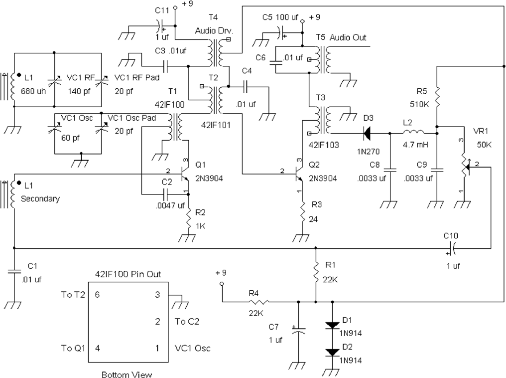
I'm going through R.Quan's book "Build your own transistor radios", and I'm triying to build one of his simple AM superhet receivers.

Since it offers many working schematics, the book is very interesting from the point of view of a novice - which I am - of RF design, but many little details are left kind of unexplained, or they're taken for granted (even though the book is supposed to be made for hobbysts/students): one of the most confusing things to me is how the author used tapped transformers to link various sections of the receiver.

While I get their most basic usage (mostly impedance matching and stepping-down of signals), I'm still scratching my head about how the author choose to connect some pins.

I have a couple examples taken from different kind of circuits in which I found the use of tapped transformers pretty confusing:

Ex. 1 enter image description here

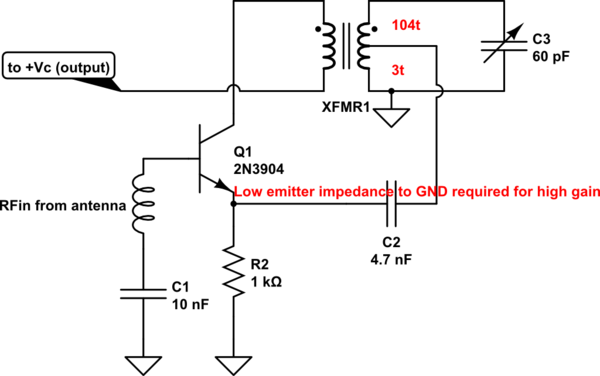
In reference to this first schematic, take the mixer/oscillator formed by transistor Q1 (2N3904) and transformer T1 (42IF100): why is the oscillator feedback signal taken from pin 2 (the middle tapped pin) of T1 instead of being taken from pin 1 (the "upper" pin)?

Looking at 42IF100's datasheet, it seems [1-2] has 104 turns, while [1-3] has 107.

The author says that tap "allows connection to the low input resistance at the emitter of Q1, which is typically less than 500 Ohms to avoid degrading the Q of the parallel resonant circuit", which is fine, but then why not connecting pin 1 instead of pin 2 to the emitter of Q1?

Where is the key advantage of connecting pin 2 instead of pin 1?

Is it just to separate the emitter of Q1 from the LC resonant circuit via the AC impedance of the coil, so that the resonant frequency doesn't get messed up?

Ex 2 enter image description here

Regarding this second example, take transformer T2 (42IF101) connected to the collector of transistor Q2 (2N3904). Let's say T2's VCC-connected pin is pin 1, middle tapped pin is pin 2 and the "floating" pin is pin 3. From 42IF101's datasheet I see [1-2] has 70 turns while [2-3] has 87, so T2 is kinda center-tapped.

I get that T2 is needed to adapt the impedance between the collector of Q2 and the low input resistance of the common emitter amplifer formed by Q3.

And since T2 has an internal cap between [1-3] that makes it also a 455 KHz filter, I then get that using a coil tap in T2 avoids loading down the Q of the LC circuit with the collector-to-emitter resistance of Q2 (given such a resistance in the order of 100 KOhms, this resistance reflects back to nodes 1-3 of T2 as 100K * n^2, being n the turns ratio between [1-3] and [1-2]).

But here are the things I find foggy: since T2 is used as a 455 KHz IF filter via the first coil and the 1-3 internal cap, how can that filtering work if pin 3 is left floating instead of being connected to ground?

And also, how can the filtering happen, if you inject the signal in the middle of the coil, thus effectively using only half of it? Doesn't that mess up the resonant frequency of the LC filter formed by the whole first coil and the internal cap?

And finally, how does that configuration effectively avoids loading down the Q of the filter (as explained before) by reflecting Q2's collector-to-emitter resistance to nodes 1-3 of T2, if [2-3] is to be considered as non-existant due to the floating connection on pin 3?

**

I'm sorry in advance if I wrote something completely off, but as I said I had to figure out myself most of the whys for the details in these circuits. I'm not really a fan of the motto "it works because it works" (which seems to be just cool among hobbysts and it also seems to be the author's approach in some key passages of the book) because it definitely leads to monkey electronics.

So thank you in advance if you took the time to give any explanation or suggestion.

\$\endgroup\$
3
  • 1
    \$\begingroup\$ Note: This is essentially a well focused question. There is a lot of detail but the answers fall in a closely related group. I'd hope that people who do not understand it pass on by and do NOT downvote it. (Past bedtime in NZ or I'd consider answering) \$\endgroup\$
    – Russell McMahon
    Commented Aug 23, 2021 at 13:07
  • 1
    \$\begingroup\$ @RussellMcMahon thank you for the feedback and clarification; I'm sorry if I posted an "ugly" question, but I'm not really used to this platform. And since I'd like to get a very detailed answer, I posted as many details as I could. \$\endgroup\$
    – Dag
    Commented Aug 23, 2021 at 13:27
  • 2
    \$\begingroup\$ I consider the question a good one. I like the detailed explanations showing what you know and seek to know. Some would see it as too unfocused and vote to close. I'm a moderator but don't get to control other people's persepctives :-). In some cases votes to close may well be based on expert opinion but in other cses people who don't know much about the subject may give it a rough skim and then vote to close. I was trying to forestall the latter. \$\endgroup\$
    – Russell McMahon
    Commented Aug 24, 2021 at 0:30

2 Answers 2

5
\$\begingroup\$

Essentially, if you want a stable oscillator (since T1 is in the LO), you want a high Q tuned circuit. Similarly, if you want sharp tuning of the RF amplifier, for good rejection of nearby interfering stations, you want a high Q tuned circuit.

And to get a high Q tuned circuit, you don't want to drain energy from it by connecting a low resistance across it.

If the emitter provides a 500 ohm load connected to pin 1, it would greatly damp the tuned circuit providing poor tuning (if it even oscillated).

Now, one thing to understand about a transformer (or autotransformer : the primary here is an autotransformer) is that because it steps voltage up or down, it steps current down or up (opposite direction) observing the law of conservation of energy.

So, if T1 steps voltage up 1:10 (there are 10 turns from pins 2:3 and 90 from pins 1:2, total 100 turns), it steps current down 10:1.

The consequence of this is, it has stepped the impedance up by 100:1. (This is the connection to "impedance matching").

So a 500 ohm load on pins 2:3 would form a 50 kilohm load on pins 1:3, allowing sharp tuning. (I'll let you work out the equivalent for a 3:107 step-up!)

#T2 likewise ... but remember that pin 3 is NOT really open! The internal capacitance is between pins 1 and 3, so this is again a tuned circuit, with Q2's output impedance stepped up by the autotransformer.

\$\endgroup\$
3
  • \$\begingroup\$ Thank you for the answer! So, correct me if I'm wrong: what you are saying is, both the examples refer to the same "strategy" of stepping up the impedance (from the emitter in the first case / from the collector in the second case) so that the resonator sees the biggest impedance possible in order to avoid "draining" it (because it would lower its effectiveness) [continues...] \$\endgroup\$
    – Dag
    Commented Aug 23, 2021 at 15:42
  • \$\begingroup\$ The only thing is, I'm not really sure I visualize how is it possible to correctly filter the signal in the second case: if the resonant frequency is obtained from the parallel of the first coil and the internal cap, shouldn't the signal be "injected" at one end of the whole coil? Or maybe it works because of the first coil acting as an autotransformer, and so when the signal is presented at the center tap, it will also be present at the whole coil (scaled up or down according to the ratio)? \$\endgroup\$
    – Dag
    Commented Aug 23, 2021 at 15:42
  • 1
    \$\begingroup\$ That's right ... pin 1 is GND (to AC, via C19) and you're applying a voltage across pins 1,2 and seeing a higher voltage across 1,3. Note that Q2 collector is a fairly high impedance so the step-up ratio need not be remotely as high as in the LO. \$\endgroup\$
    – user16324
    Commented Aug 23, 2021 at 15:45
3
\$\begingroup\$

Where is the key advantage of connecting pin 2 instead of pin 1?

Is it just to separate the emitter of Q1 from the LC resonant circuit via the AC impedance of the coil, so that the resonant frequency doesn't get messed up?

Yes, a low tap point keeps oscillator resonator Q high, but there's another reason for a very low tap point. In this transformer, there are 3 turns out of 107 between emitter-to-ground. Those 3 turns present a low impedance to the emitter as the author has pointed out. Why is this necessary?....

Keep in mind that this is a mixer having two signal inputs (actually three):

  • RF antenna signal (1MHz into base)
  • Local oscillator signal (1.455 MHz into emitter)
  • Audio (into base, riding along with RF)

For the moment, forget the audio - it can be considered separate from the two (much) higher frequency RF signals and only complicates RF circuit operation.
Since there are only two active stages having gain, every effort has been made to optimize circuit impedances so that gain is large.
Q1 is a mixer with gain, not only to allow Q1 to oscillate at 1.455MHz, but to amplify small 1 MHz signals coming in to its base. You can look at Q1's functions separately as an oscillator or as an RF amplifier. However, keep in mind that it must operate non-linearly so that the stage's output of interest is at 0.455 MHz, rather than at 1 MHz....resulting mixer gain is some fraction of what it would be if it was a straight amplifier (1MHz in, 1MHz out). We can maximize mixer gain by maximizing RF gain.

schematic

simulate this circuit – Schematic created using CircuitLab

Consider Q1 as RF amplifier, forgetting for a moment that it is oscillating at 1.455 MHz too. For high gain, the 1MHz input signal at its base would see a very low impedance from emitter to ground. Ideally, emitter would be AC-grounded, perhaps with capacitor C2 (4.7nf), were it not a mixer.
Instead, emitter is grounded through C2, in series with 3 turns of T1. The impedance of those three turns is necessarily small, so that impedance from emitter to ground is small as far as the RF input signal at 1 MHz is concerned. Small base input current is amplified to larger collector-emitter current in Q1 when impedance at emitter is low.

\$\endgroup\$
2
  • 2
    \$\begingroup\$ This radio circuit is seemingly simple (only 2 transistors), but a poor one to study, since multiple signal frequencies flow through. Keeping track of component function gets complicated with multiple signal frequencies (mixer operation is hard enough to study with only two signals in the same stage). Reflex radios that combine RF & audio like this one add too much complexity for studying fundamentals. \$\endgroup\$
    – glen_geek
    Commented Aug 23, 2021 at 14:27
  • 2
    \$\begingroup\$ Thank you! It makes sense. So, if I got your answer correctly, there are 2 reasons for the use of the tapped coil in the first example: 1) to avoid degrading the Q of the resonator by AC decoupling the emitter from the parallel of L and C. 2) to basically obtain in one go both the emitter AC grounding of the amplifier for the 455 KHz IF signal from the mixer (since the emitter resistance lowers the gain) and the feedback path necessary for the oscillation. \$\endgroup\$
    – Dag
    Commented Aug 23, 2021 at 14:30

Your Answer

By clicking “Post Your Answer”, you agree to our terms of service and acknowledge you have read our privacy policy.

Not the answer you're looking for? Browse other questions tagged or ask your own question.