Background Info: I need to drive two 24VDC brushed motors (SDS4360-24-120F) with a dual H-bridge circuit using 5V control signals. Initially a few L298N module were used but they all eventually fried up sometime during operation. It all happened randomly whenever I sent the command to change rotation direction at full speed. The datasheet said the motor has a 5A peak startup current so I'm assuming that's what killed the L298N module.
Alternative H-Bridge IC: From looking around, the only H-bridge ICs that met the voltage and current requirement are the MC339321VW/MC33932VW. The problem is that it's a bit pricey at $34.77 CAD per unit. So I decided to look into building my own H-bridge circuit using P-FET and N-FET.
Initial Idea:
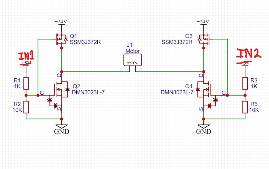
I followed this video from Afrotechmods and built a circuit in the picture below. The N-FETs are the DMN3023L-7 and the P-FETs are the SSM3J372R,LF. Both can handle a 30V difference between source and drain. From what I can find, the problem is the Vgs difference on the P-FET is too large. The difference can be as large as -24V compared to the -12V max rating on the datasheet. So I came up with this new design.

Current Design:
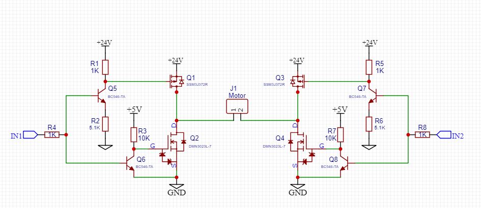
I added NPN BJTs in the current design (picture of it below). The idea is if IN1 is low, Q5 and Q6 are low (aka the switch is open). Thus, Vgs on P-FET is 0V so it's off (open) and Vgs on N-FET is 5V so it's on (closed). When IN2 is high, Q5 and Q6 are high. The gate on the P-FET is connected to voltage divider giving it around 20V which makes a Vgs of -4V. Thus the P-FET is on (closed). The gate of the N-FET is connected to ground and thus, it's off (open). I can't seem to find any fault with this design. If you guys do please, let me know!

