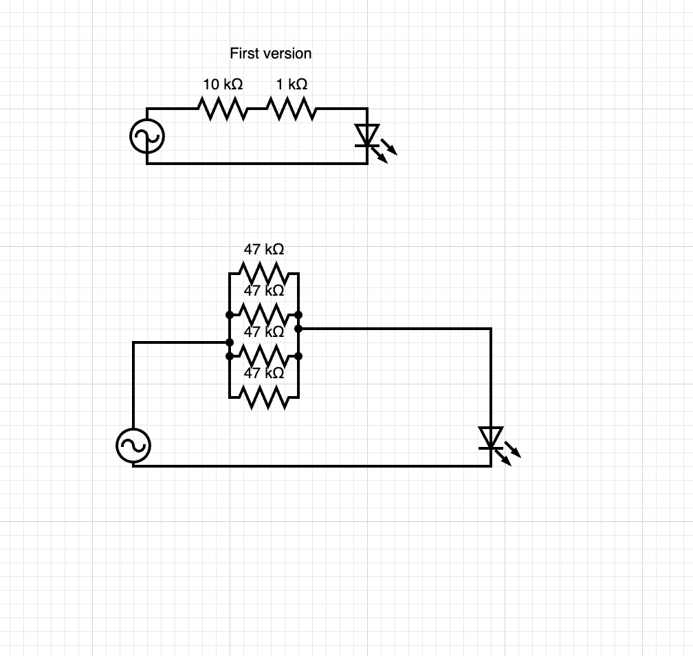
I have designed a dead simple LED circuit I calculated the required resistance to be (220-2)/0.02 = ~11k so I used 10k+1k resistors in series but for some reason, the 10K resistor started smoking in like 10 seconds although I estimated the power usage to be 2 V*0.02 A = 0.04 W which is way below the rated power of my resistor.
On the second circuit, I used 4 47k resistors in parallel so I get a resistance around 12k this time the resistors did not burn but still got very hot.
I can't understand what I'm missing or I don't know exactly.

-
4\$\begingroup\$ This is not the way to operate an LED at 220 V AC. Indeed the resistors will get too hot, that could be solved by using resistors with a higher power rating. Another problem is that an LED doesn't like it when you're applying a reverse voltage across so it will breakdown and might suffer damage. Watch this video and let BigClive show you what circuit to use: youtube.com/watch?v=Q23uh7AjjXw \$\endgroup\$– BimpelrekkieCommented Nov 15, 2021 at 19:34
-
2\$\begingroup\$ 2.5W resistor should dissipate. 218*0.02=4.36. And current flows only half wave. But another halfways will burn your LED, because a max negative voltage 5V, you have 310V. \$\endgroup\$– user263983Commented Nov 15, 2021 at 19:39
-
1\$\begingroup\$ Try doing the same calculation for the 309 V across the 11kΩ resistor. (The peak voltage for 220VAC is actually quite a bit higher than 220VDC: VDCpeak = VACrms * √2 ≅ VACrms * 1.414 ⇒ 220VAC * √2 ≅ 311 VDC ) \$\endgroup\$– Alex HajnalCommented Nov 15, 2021 at 19:40
4 Answers
First: Your power calculation isn't correct. 2V*0.02a = 0.04w is the calculation if you had 2 volts across the resistor. You don't. You have approximately1 220 - 2 = 218 V. The power dissipation is hence roughly 4.4 W if conducting throughout the AC cycle.
Additionally: LEDs aren't intended to withstand a large reverse voltage. On the negative cycle of the waveform, the LED initially has no current through it, so there is no voltage drop across the resistors. This places up to 220 V * sqrt(2) = 311 V of reverse voltage across the LED, destroying it almost instantly (they are designed to handle around 5 V or so of reverse voltage).
You'll can add a shunt diode which will also protect the LED. It can also be a second LED, in which case you twice the light - one lights on one half-cycle, one lights on the other half-cycle. Of course, twice the resistor current means twice the resistor power dissipation.
Additionally, be very careful with mains circuits in general as they can be extremely dangerous to you and your home (as they can electrocute, start fires, etc). Based on the mistake you're currently making here, I strongly suggest that you practice with battery powered circuits instead - while you may still destroy components, you do not risk deadly electric shocks or house fires. Thankfully, this mistake did not lead to a fire, although it had a risk of doing so (unless you use special flame-proof resistors which are guaranteed not to burn down your home if overloaded).
A much deeper and more accurate understanding is necessary to safely work with 220 VAC (or 110 VAC).
1 Approximate, because in reality 220 is Vrms and we're subtracting an offset of 2 V.
-
3\$\begingroup\$ 220V is not something you should toy around with. Just for the sake of emphasis: you made very-very basic mistakes, which lead me to believe that you are a total novice at electronics. That's fine, nay, excellent: you decided to learn something new, which is to be applauded. But I'd suggest you start your journey with max 12V batteries and stay clear of mains AC voltages until you really know what you're doing. And even then be very-very careful and consult more knowledgeable people before plugging anything in. \$\endgroup\$– pfabriCommented Nov 15, 2021 at 20:03
-
\$\begingroup\$ @pfabri I think you added this to the wrong comment box - adding a comment here won't lead to an entry in op's inbox. I'm personally well-familiar with the dangers of mains AC (hence writing my answer in this way) and even then I take great care (proper PPE, suitable fire extinguisher, current limiting, thorough simulation, etc) when I occasionally do need to work with these voltages. \$\endgroup\$ Commented Nov 15, 2021 at 20:08
-
1\$\begingroup\$ Your suggestion about the series diode - much better to suggest a shunt diode, then it only has to withstand 3 V, although then the resistors get twice as hot. If the shunt diode is another LED, then you get the twice the light for twice the resistor heat. \$\endgroup\$– Neil_UKCommented Nov 15, 2021 at 20:18
-
\$\begingroup\$ @nanofarad True, I realised that, but I think it segues into the things you brought up in your answer. I think you were clear enough I just wanted to second your message. \$\endgroup\$– pfabriCommented Nov 15, 2021 at 20:26
-
\$\begingroup\$ @Neil_UK Updated. thanks for the suggestion. \$\endgroup\$ Commented Nov 15, 2021 at 20:28
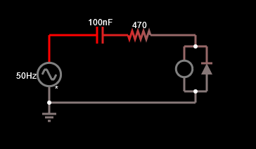
LED 'dropper' circuits typically add a series capacitor to add some impedance, and a reverse diode across the LED to protect the LED it from overvoltage.
Good starting point: 0.1uF with some series resistance to select for peak current of about 10mA. You'll see that the addition of the cap allows you to reduce the resistor wattage considerably.
Try this simulation (simulate it here):
First, the capacitor. The 0.1uF in series adds about 32kohms impedance at 50Hz. The capacitor alone across the line corresponds to 10mA peak at 230VRMS / 325V peak. That's about perfect for the LED. You can increase or decrease the LED current by adjusting the capacitor value.
With this capacitor impedance the resistor is practically unnecessary, but we can keep it around and decrease its value. Thus, almost no power is dissipated in the resistor (only about 50mW max in the sim) because it's only dropping a few volts instead of nearly the full line voltage as in your design. Instead, all the dropping happens in the capacitor, and being a capacitor uses no real power while doing that.
Compare with your circuit. 11k ohms across 230V RMS dissipates 4.8W RMS in the resistor. Not only does this kill the resistor pretty quickly, but it wastes a lot of power. Yikes.
Second, the reverse diode. This is essential. Without it, the voltage across the LED will build up until it reaches its reverse breakdown and dies. That's at least one thing that happened in your circuit. You can also use 2 LEDs back-to-back and get twice the brightness.
In any event, build with caution and enclose completely to prevent anyone coming into contact with the live voltage.
220 VAC was standardized in Europe as 230 VAC about 15 years ago.
230 VAC is the effective value and not the peak value.
The actual value that you measure using a scope is:
Vmains(t) = 1.414 * 230 * sin(6.28 * 50 Hz * t)
that is
Vmains(t) = 325 * sin(6.28 * 50 Hz * t)
So you have a peak of 325 Volt. Keep that in mind when selecting your resistors. Not all resistors are able to withstand 325 Volt.
If you plan to measure the mains voltage by a scope, I strongly suggest you to put a 1:1 transformer or 1:n between the mains and the probe of the scope.
Infact, the probe's crocodile is connected to Earth and you don't want to short to Earth the Live or Neutral wires.
I estimated the power usage to be 2 V × 0.02 A = 0.04 W which is way below the rated power of my resistor.
You calculated the power dissipated in the LED instead of the power dissipated in the resistor!

