3
\$\begingroup\$

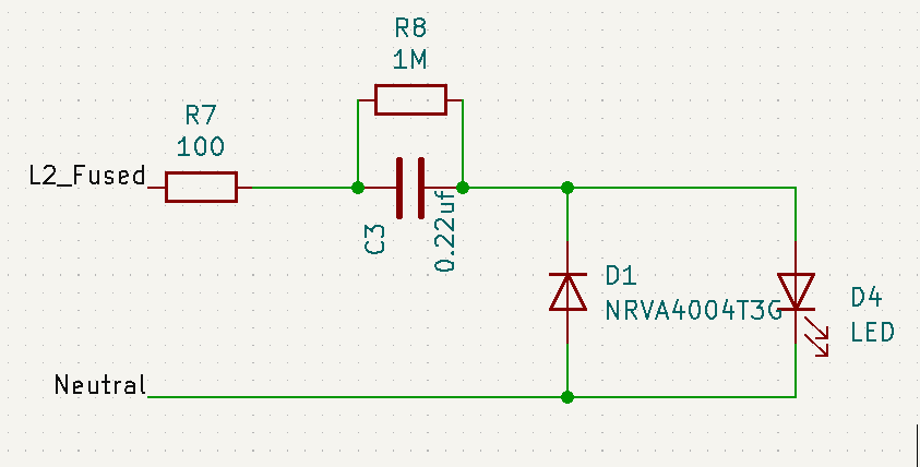
I am using the circuit below to indicate the status of a 230V AC line.

This works well when I apply power to it. The LED is on with a good brightness.

However if I switch the main on and off and back very quickly the 100 Ω resistor (R7) gets fried. I have made several circuit of the kind and checked all polarity etc. This is mounted on PCB. Replacing the resistor make the circuit good again but if I dare switching the power too quickly it does the same again.

Any idea what could cause this?

enter image description here

\$\endgroup\$
3
  • 1
    \$\begingroup\$ My conclusion. Using a LED to indicate power ON from mains is a bad idea. These are the reasons. * Complex circuit prone to weakness. * Could be unsafe if failing while power to application is still ON. * Potential hidden issues (like fast power switching frying something). * Too many components * Hard to source components. (pulse proof resistors) * Potentially expensive components. * All of these making the final product hard to manufacture. My solution. Using a neon bulb with a resistor. * Simple. 2 components. * Cheap. * Easy to diagnose. * No hidden issues. \$\endgroup\$
    – Noel
    Commented Jul 14, 2023 at 8:33
  • \$\begingroup\$ and I forgot to add. The footprint on a PCB of this solution is way bigger than just the neon bulb + resistor. Especially that bulky capacitor. \$\endgroup\$
    – Noel
    Commented Jul 14, 2023 at 14:47
  • \$\begingroup\$ neons definitely have their uses, even today. However you might be amused that I remember a transistor-based computer that used neons for the register displays etc.: despite requiring around 100V they were more reliable than incandescent bulbs, and LEDs hadn't yet been invented. \$\endgroup\$ Commented Jul 14, 2023 at 14:50

3 Answers 3

6
\$\begingroup\$

As an alternative to the answer by GodJihyo, here is another way of looking at the problem.

When the power is off, R8 discharges C3. So the voltage across it is zero. The voltage drop in the diodes is negligible when compared with 230V.

The peak voltage of 230V AC is about 325V.

So at the moment you turn on the power, pretty much the entire supply voltage is across R7. That voltage could be anything between 0V and 325V. Using P = V²/R, for a fraction of a second, the power dissipated in R7 could be anything between 0W and 1000W.

Once C3 reaches the supply voltage, its impedance limits the current, and R7 cools down.

But if you keep turning the power off and on very rapidly, R7 gets hit by a rapid succession of power surges, and fries.

\$\endgroup\$
2
  • \$\begingroup\$ Thank you for getting back. How to avoid it then? Should I increase the resistor value or power capacity? \$\endgroup\$
    – Noel
    Commented Jul 13, 2023 at 17:20
  • \$\begingroup\$ @Noel consider both options. A higher value resistor will reduce the inrush, but it will get warmer in normal use. \$\endgroup\$
    – Simon B
    Commented Jul 13, 2023 at 19:36
5
\$\begingroup\$

At line frequency the capacitor has a high enough impedance to limit the current, but when switching on and off quickly you can create transients at higher frequencies where the capacitor impedance is low. This can allow enough current to flow to exceed the resistor's ratings, and eventually the LED may also be damaged.

At 60 Hz 0.22\$\mu\$ will have an impedance of around 12k\$\Omega\$, limiting the current to around 20 mA. If the resistor is 1/4 W the maximum current it can handle will be $$ \sqrt{\frac{0.25 W}{100\Omega}} = 50 mA $$ For a 1/2 W resistor it's around 70 mA, and for 1 W it's 100 mA. So it doesn't take a lot of extra current to burn up the resistor, just raising the frequency to 180 Hz would make the capacitor's impedance around 4k\$\Omega\$ and be enough to blow a 1/4 W resistor.

\$\endgroup\$
3
  • \$\begingroup\$ Thank you for getting back. How to avoid it then? Should I increase the resistor value or power capacity? \$\endgroup\$
    – Noel
    Commented Jul 13, 2023 at 17:20
  • 1
    \$\begingroup\$ @Noel I would take Kuba's suggestion about making it a 3W pulse withstanding resistor. \$\endgroup\$
    – GodJihyo
    Commented Jul 13, 2023 at 17:51
  • 1
    \$\begingroup\$ @Noel The resistor could be increased and capacitor reduced while still giving enough current for the LED to light up. 5mA is plenty for most LEDs. \$\endgroup\$
    – jpa
    Commented Jul 14, 2023 at 6:57
2
\$\begingroup\$

R7 needs to be a pulse-withstanding 3W part. Through-hole would keep the heat off the PCB. Nowadays several very good SMD pulse-withstanding pets are available so both should work. It will probably survive your tests then.

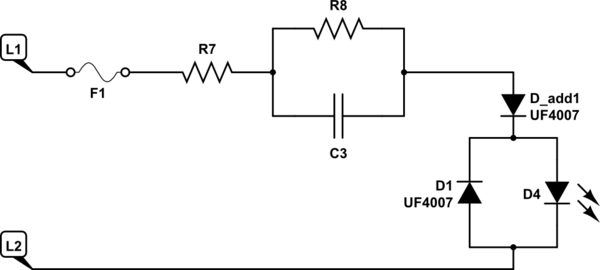
D1 could be in series with the LED, not across it. It should be UF4007. The rectifier you have there is too slow and not really rated for the application. The LED could be overstressed and fail because of it.

There still should be an anti-parallel rectifier across the LED, but one in series with the two is needed as well. Both can be UF4007 to keep the number of BOM lines down.

schematic

simulate this circuit – Schematic created using CircuitLab

\$\endgroup\$
5
  • \$\begingroup\$ Thank you. Hard to find a 3W pulse resistor. Mouser has 1W only. Will keep searching. Would you put the additional series diode in the same direction has the led then? \$\endgroup\$
    – Noel
    Commented Jul 13, 2023 at 19:24
  • 1
    \$\begingroup\$ You can try two 1W 200ohm pulse rated resistors in parallel. \$\endgroup\$ Commented Jul 13, 2023 at 19:26
  • 1
    \$\begingroup\$ @Kubahasn'tforgottenMonica Why do you need the extra diode? Having it there will completely alter the operation of the capacitive dropper. \$\endgroup\$
    – Simon B
    Commented Jul 13, 2023 at 19:37
  • 3
    \$\begingroup\$ @SimonB I'd go as far to change "completely alter" to "render effectively useless". Also I challenge the notion that any change to the diodes is even necessary; I don't see how the diode would be too slow for the application (and that's ignoring the fact that 1n400x parts usually have pretty short forward recovery time). \$\endgroup\$
    – marcelm
    Commented Jul 13, 2023 at 22:28
  • 1
    \$\begingroup\$ With D_add1 in series, there is no discharge path for C3 except through R8. This will result in much smaller current passing through the LED. \$\endgroup\$
    – jpa
    Commented Jul 14, 2023 at 6:53

Your Answer

By clicking “Post Your Answer”, you agree to our terms of service and acknowledge you have read our privacy policy.

Not the answer you're looking for? Browse other questions tagged or ask your own question.