1
\$\begingroup\$

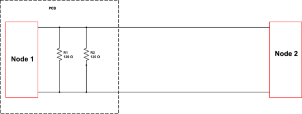
Can someone please explain to me why this is the wrong way to set up a CAN bus?

When I measure the resistance between CANH and CANL I get 60Ω, so why must I put the termination resistor on node 2 when I can just terminate the bus on the PCB itself like shown here?

schematic

simulate this circuit – Schematic created using CircuitLab

\$\endgroup\$
3
  • 3
    \$\begingroup\$ Because then the bus at node 2 will not be terminated. It's like preventing the rope from fraying by tying two knots on one end. \$\endgroup\$
    – Maple
    Commented Nov 27, 2021 at 0:25
  • \$\begingroup\$ From where, you came across this termination \$\endgroup\$
    – Mitu Raj
    Commented Nov 27, 2021 at 0:30
  • \$\begingroup\$ @MituRaj More interesting question - why wasn't the idea followed to it's "logical" end of using one 60 Ohm resistor? \$\endgroup\$
    – Maple
    Commented Nov 27, 2021 at 0:33

2 Answers 2

4
\$\begingroup\$

You've measured the DC resistance of the bus, and indeed to a DC signal the 120 ohm resistors can be anywhere on the line. Not so much for fast signals.

The need for termination follows transmission line theory, so the lumped circuit approximations of those resistors in parallel go completely out the window. In reality, you're dealing with edges that are fast enough that they take time to travel through the cable and don't appear at both nodes and/or both resistors at the same time. This question's answers (both mine and others) discuss this in detail.

The actual structure of the correctly-terminated bus is not exactly the following:

schematic

simulate this circuit – Schematic created using CircuitLab

Rather, it more closely resembles the following:

schematic

simulate this circuit

Each end of the transmission line must be matched to the appropriate impedance to properly terminate the line and prevent reflections. Reflections cause signal integrity issues by turning sharp, clean edges into a messy signal.

\$\endgroup\$
2
\$\begingroup\$

This would work for a short network of less than a couple of meters but for anything longer or with more than two nodes it would allow reflections on the bus that could compromise data integrity.

when a signal transition reaches the end of the line it will reflect if the termination does not match the characteristic impedance of the line (120 ohm).

The reflection will then travel back down the line to the other end. If the other end of the line is terminated with 60 ohm there will be a smaller reflection there as the reflection amplitude is determined by the difference between the line impedance (120) and the termination (60 ohm in this case).

The reflection will bounce back and forth until it is absorbed by losses and the (incorrect termination). All this time though the receivers will get incorrect signal.

If the bus is very short (eg the time of travel is less than the transition time) then the reflections will not have significant effect and the system will act normally. So for testing on a bench with a moderate speed network it can work with both terminations at the same end, but for longer networks it is necessary to follow the termination rules.

CAN Physical Layer Requirements
\$\endgroup\$
3
  • \$\begingroup\$ So why are they reflections in the wire even after I measure 60ohms on the bus? How does the electrons know where the termination resistor is placed? Why does the placement of the termination resistor matter in longer or more than two nodes matter, especially since the electrons flowing only sees 60os resi \$\endgroup\$
    – JoeyB
    Commented Nov 27, 2021 at 0:40
  • \$\begingroup\$ How does the circuit know where the termination resistor is placed in order to cause these reflections \$\endgroup\$
    – JoeyB
    Commented Nov 27, 2021 at 0:41
  • 1
    \$\begingroup\$ @JoeyB - when a signal transition reaches the end of the line it will reflect if the termination does not match the characteristic impedance of the line (120 ohm). The reflection will then travel back down the line to the other end. If the other end of the line is terminated with 60 ohm there will be a smaller reflection there as the reflection amplitude is determined by the difference between the line impedance (120) and the termination (60 ohm in this case). The reflection will bounce back and forth until it is absorbed by losses \$\endgroup\$ Commented Nov 27, 2021 at 1:00

Your Answer

By clicking “Post Your Answer”, you agree to our terms of service and acknowledge you have read our privacy policy.

Not the answer you're looking for? Browse other questions tagged or ask your own question.