1
\$\begingroup\$

I'm trying to create a low-noise 3.3V power supply to power an ADC. The TI TPS7A53 LDO seems like a good option for this. It has low noise of 4.4 μVRMS and a worst-case PSRR of 10 dB for an input frequency of 2 MHz and 3.3V output voltage.

I hooked up the circuit as follows:

enter image description here

Turning everything on, I see a voltage drop across the LDO but a significant amount of noise on the output.

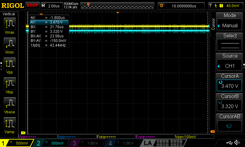
In this figure the buck converter output is in yellow and the LDO output is in blue:

enter image description here

The voltage drop across the LDO is 150 mV, which is larger than the worst case dropout of 110 mV (datasheet, Fig. 20).

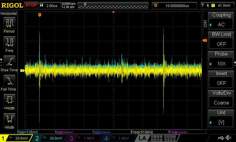
Switching the oscilloscope probes to AC-coupled, and zooming in on the noise, we see the following:

enter image description here

The noise on the output consists of two components: (i) a large spike about every 17 us, and a significant amount of lower-amplitude high-frequency noise. The LDO (shown in blue) is not filtering the input noise in any way, and actually appears to be making the p-p amplitude of the switch spikes worse. This appears to be 0 dB PSRR.

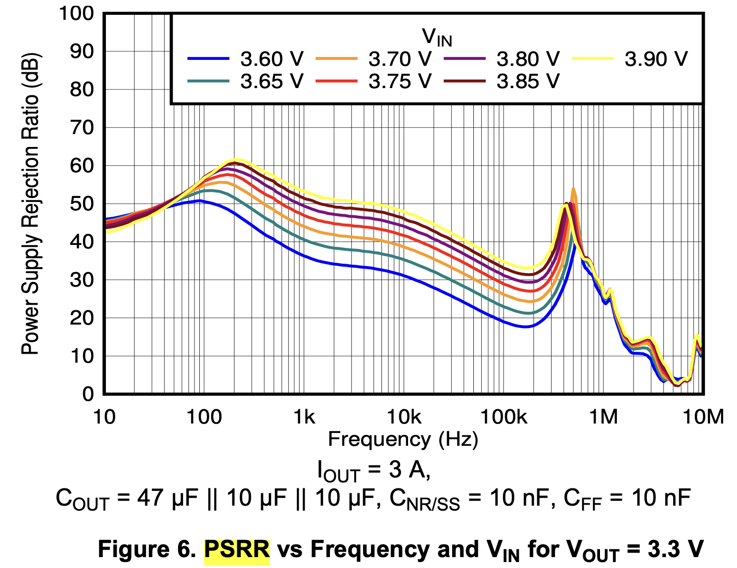
Why are we not seeing the 10 dB or more of PSRR promised by the datasheet? The figure in question is Figure 6:

enter image description here

This seems to suggest that even high frequency switch transients (10 MHz+) should see 10 dB of attenuation.

Am I misunderstanding something? Why isn't the LDO filtering my switched power supply output? Thanks.

\$\endgroup\$
3
  • 7
    \$\begingroup\$ Maybe the LDO does filter, but you are just having bad PCB layout or have connected the in a way that picks up switching noise? Please post PCB layout and photo how you connected probes and ground clips to PCB? \$\endgroup\$
    – Justme
    Commented Apr 7, 2022 at 18:00
  • \$\begingroup\$ If you had more voltage headroom, I would suggest using a capacitance multiplier. \$\endgroup\$ Commented Apr 7, 2022 at 19:33
  • 1
    \$\begingroup\$ Layout? Decoupling? Probe setup? \$\endgroup\$
    – winny
    Commented Apr 7, 2022 at 20:06

2 Answers 2

3
\$\begingroup\$

"Why isn't the LDO filtering my switched power supply output?"

Sometimes voltage regulators get seen as magic voltage slicers, that cut the top off the input voltage graph and leave a lovely flat line out.

The LDO regulator (rather than 'LDO') should not be used as a filter. Like many components, it has filtering characteristics but that's not its strength or purpose. It'll reject low frequency variations but that's about it. High frequencies will go pretty-much straight through it.

Instead, the regulator's input waveform should be filtered to clean it up first. That filter can be as simple as parallel capacitance or a series/parallel filter such as a Pi filter (C-L-C).

Make sure the LDO regulator has decoupling capacitors for output filtering.

enter image description here

\$\endgroup\$
5
  • \$\begingroup\$ Thanks very much for the reply. "The LDO regulator ... will not filter anything." When I look at the datasheet, I see a part with a PSRR of at least 10 dB increasing to 20-40 dB at common switch mode PS frequencies of 100-200 kHz. I'm surprised that they quote PSRR for a part not intended to filter anything. Why give that figure then? \$\endgroup\$
    – bcattle
    Commented Apr 7, 2022 at 18:20
  • \$\begingroup\$ Of course it does filter, it's a feedback amplifier. And it has a defined and specified frequency response, not only over "very low frequencies". \$\endgroup\$
    – hobbs
    Commented Apr 7, 2022 at 18:24
  • \$\begingroup\$ @Hobbs, yes, that was bad phrasing, changed now. But the point stands: a regulator should not be used as a filter component in a power supply but should be supplied with a filtered input with lower (low frequency) ripple. Whatever the individual part characteristics, that engineering direction is shown in practically all power supply designs/units you'll find around. \$\endgroup\$
    – TonyM
    Commented Apr 7, 2022 at 19:32
  • 1
    \$\begingroup\$ @bcattle Those spikes are hundreds of MHz in bandwidth which is beyond what the regulator can reject. Also, your ground connection on your oscilloscope probe could be causing issues. Try connect the ground ring of the scope probe as directly as possible (don't use the ground lead on the probe!) to ground and see if that improves things. The ground lead on a probe can cause issues when dealing with fast edges. \$\endgroup\$
    – qrk
    Commented Apr 7, 2022 at 19:34
  • \$\begingroup\$ The lowest frequency that Buck converter can run at is 250 KHz, but the trace shows noise with a period of ~9 microseconds (110 KHz), so I'm skeptical of the assumption that we are seeing switching noise. I wonder if the probes are being used correctly? \$\endgroup\$ Commented Apr 7, 2022 at 22:55
2
\$\begingroup\$

You haven't said anything about the capacitors in your design. Those need to be adequate to give a stable output. The data sheet should have suggestions.

You've given the LDO a tiny voltage margin to operate with. Looking at those scope traces, I wonder if the noisy input voltage is dropping so low that the LDO can't even regulate any more. Is there any reason why you aren't feeding it something like 3.90V, which seems to give a better result on the graph you posted?

\$\endgroup\$

Your Answer

By clicking “Post Your Answer”, you agree to our terms of service and acknowledge you have read our privacy policy.

Not the answer you're looking for? Browse other questions tagged or ask your own question.