2
\$\begingroup\$

I've been researching parallel plate capacitors but couldn't find many experiments on how long a sealed parallel plate capacitor could possibly hold its charge and why.

To experiment, I ordered a 5 cfm vacuum generator w/chamber and plan on putting a copper parallel plate capacitor inside it at around 30 Hg. The plates have an area of 0.049 m², are about 1 mm thick, and about 7 mm apart. After charging it to, say, 15 V and disconnecting the leads, I'm wondering how long the charge will hold and why.

Any thoughts what'll happen? Any feedback is greatly appreciated!

\$\endgroup\$
10
  • 1
    \$\begingroup\$ What are you using for any solid insulators? (hint, PTFE would be good). What are you using to measure the voltage? (hint, nothing would be best, with only an occasional connection to a high impedance meter) (or check out Rob Pease, femto-amp amplifiers). \$\endgroup\$
    – Neil_UK
    Commented Sep 6, 2022 at 20:07
  • 2
    \$\begingroup\$ How close are you to Chornobyl? Windscale? Fukushima? the stratosphere? \$\endgroup\$
    – user16324
    Commented Sep 6, 2022 at 20:17
  • 3
    \$\begingroup\$ Is that meant to be 30 mm Hg (which would about 4 kPa)? \$\endgroup\$ Commented Sep 6, 2022 at 20:26
  • 2
    \$\begingroup\$ PTFE works down to fA current range, then sapphire insulators should be used. Leak causes will include: light due to photoeffect, residual gas conductivity (very low, usually hydrogen and little water at UHV), ionizing radiation which creates conductive tracks in insulators and residual gas and also causes photoeffect. At such experiment i can only imagine good old mechanical electrometer, dynamometer or resonant capacitor. \$\endgroup\$
    – Vladimir
    Commented Sep 6, 2022 at 21:35
  • 1
    \$\begingroup\$ @HelloCthulhu, what does "It's about 30 Hg," mean? Are you stating the vacuum bellow ambient pressure? If so, that is not a true "vacuum" capacitor. Consider the pressure in a vacuum tube (valve), far less than 1/10,000 Tor,, achieved using mechanical rotary pumps backing an oil diffusion or turbomolecular pump, and then a "getter" to absorb trace gases. See hackaday.com/2014/11/21/… \$\endgroup\$ Commented Sep 6, 2022 at 22:03

1 Answer 1

2
\$\begingroup\$

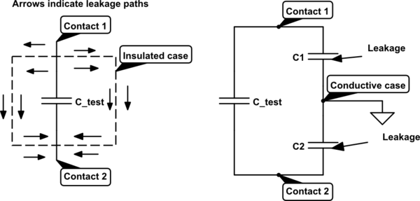
The leakage between the plates is essentially zero. You can calculate using the resistivity of air and the volume between the plates. By reducing the air pressure, the resistivity will increase.

The primary leakage path is along the surface of the of the vacuum container, both the inner surface and the outer surface. If the container is conductive then the insulated contacts will form additional capacitance with the one under test.

schematic

simulate this circuit – Schematic created using CircuitLab

How long it will hold charge is determined by the choice an cleanliness of the insulating materials.

Of course, the voltmeter (electrometer) will also add R,L and C that may be the main source of leakage.

Looks like a fun experiment. The physics SE may have some suggestions.

\$\endgroup\$

Your Answer

By clicking “Post Your Answer”, you agree to our terms of service and acknowledge you have read our privacy policy.

Not the answer you're looking for? Browse other questions tagged or ask your own question.