9
\$\begingroup\$

enter image description here

A parallel plate capacitor consists of two parallel conductors with opposite charges. In the above diagram, the wires are parallel and conductors so do they act as capacitor plates?

If they do, if you have two wires right beside each other, and connect a capacitor to the end, would the capacitor still charge as much? Since the whole thing acts as one big capacitor, the charge wouldn't just gather at the capacitor, it would spread out over the whole wire and the capacitor, meaning there would be less charge in the capacitor.

And if this is true why doesn't the equation for capacitance take the position of the wires into account?

enter image description here

\$\endgroup\$
13
  • 5
    \$\begingroup\$ Why yes, wires have capacitance associated with them. It's often called parasitic capacitance (look it up). Often, the parasitic capacitance of the wire is small enough, and it can be ignored. In other cases, parasitic capacitance can not be ignored. \$\endgroup\$ Commented Jan 31, 2014 at 22:18
  • \$\begingroup\$ Capacitance of wires in fairly close proximity might be 20pF/foot (30cm). If your parallel-plate cap is much bigger than the capacitance you may be able to ignore the wire capacitance. A home-made adjustable capacitor made with twisted wires is often called a "gimmick capacitor". \$\endgroup\$ Commented Jan 31, 2014 at 22:24
  • 2
    \$\begingroup\$ With a voltage source, there is not any less charge on the capacitor. There's just a tiny additional charge on the wires, too. \$\endgroup\$
    – Dave Tweed
    Commented Jan 31, 2014 at 22:29
  • 1
    \$\begingroup\$ Pedantic here, wires on a pcb are not wires. They are traces (or jumpers). And they do have insulation in the form of the pcb (like fr4) and soldermasking. \$\endgroup\$
    – Passerby
    Commented Feb 1, 2014 at 1:41
  • 1
    \$\begingroup\$ If you run an insulation test (high voltage earth to live/neutral) on a piece of equipment with a rubber cable, then touch the plug, you will very rapidly discover that pairs of wires (in a cable) are efficient capacitors. \$\endgroup\$
    – abligh
    Commented Feb 1, 2014 at 13:12

7 Answers 7

11
\$\begingroup\$

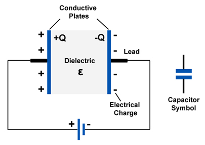
Two wires do make a capacitor. Just a very small one. For parallel plates, capacitance can be calculated as:

$$ C = \frac{\varepsilon A}{d} $$

Where:

  • \$\varepsilon\$ is the permittivity of the dielectric, which is mostly air for some wires, with \$\varepsilon \approx 8.85 \cdot 10^{-12} \mathrm F/\mathrm m\$.
  • \$A\$ is the area of the plates
  • \$d\$ is the distance between the plates

For two ordinary wires in a circuit, \$A\$ is very small, and \$d\$ is very large, compared to the distances in your typical capacitor. Thus, the capacitance is really, really small, and we can neglect it in most cases.

As for your second question, you have to be careful about the words you use. Does charge mean electric charge or how much energy you've stored in the capacitor? I'm not the only person frustrated by the contradictory vocabulary around capacitors. I'll do my best to be clear.

The charge imbalance does spread out along the wire, in one sense. Between the battery terminals, or between any two points along the wire, or between the plates of the capacitor, you will measure the same potential difference with your voltmeter. The electric field exists not only between the plates of the capacitor, but between the two entire halves of the circuit.

Inside the capacitor, the electric field must change from the potential of one half to the potential of the other half within a very tiny distance, just the separation of the plates (\$d\$ from above: it's tiny to make a high capacitance). Thus, the field strength, measured in volts per meter, is highest inside the capacitor.

As far as where the electric charge goes, think of it this way: half of the circuit has too many electrons, and the other half of the circuit has not enough. When there are too many electrons, they want to move to someplace where there are less, because like charges repel. So for the half with too many electrons, the closest they can get to a place where there are less electrons is inside the capacitor, because it's closest to the other half of the circuit.

Not all the electrons pile up in the capacitor, mind you, because that would leave the wire with a positive charge. Rather, the electrons redistribute themselves so that the potential difference (voltage) is the same everywhere in that half of the circuit. Most of the excess electrons end up in the capacitor, precisely because this is where the electric field is strongest.

You can also think about this for the opposite half by considering the absence of an electron to be a "hole", a sort of positive charge carrier.

You can also think about how the electric charges distribute themselves this way: we already established that the wires have a very low, but non-zero capacitance. Capacitance \$C\$ is just another way of saying how much charge \$Q\$ it takes to make a voltage \$V\$ in a thing:

$$ C = \frac{Q}{V} $$

The wires, having a low capacitance, don't take much electric charge imbalance (extra or missing electrons) to make a big change in voltage. The capacitor, having a large capacitance, takes much more charge imbalance to change the voltage. Thus, to make the voltages equal across each half of the circuit, most of the imbalanced charge must end up in the capacitor, not the wires.
\$\endgroup\$
7
\$\begingroup\$

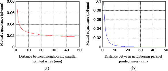
The problem is more serious than you describe, because there is not just a capacitance but an inductance and resistance as well, that are changing all your design at their resonance frequency. A nice tool to calculate the capacitance of two parallel wire is the QuickField and you can download the Student Edition for free.

In PCB traces some typical values for capacitance and inductance are

enter image description here

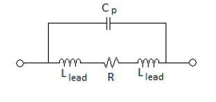
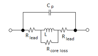
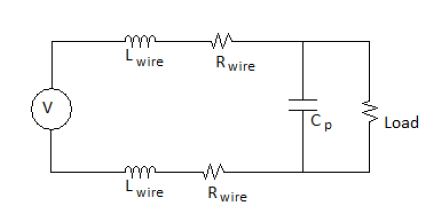
As you can see there is a big problem especially in high frequencies. This parasitic elements are everywhere, and engineers must taking into account according to the application main parameters (frequency, voltage etc). You can see bellow the main passive elements non ideal equivalent circuit that introduce limitations in using them .

Resistor

enter image description here

Capacitor

enter image description here

Inductor

enter image description here

Wires and Transmission lines

enter image description here

Smaller component sizes usually result in smaller parasitics. With today SMD passive components on PCB allow for several GHz safe design. In wires, transmission lines technics are using (coax, twisted pair, ribbon cables, twin lead, microstip and stripline…)

\$\endgroup\$
1
  • \$\begingroup\$ Trch the y-axis of the right diagram is inductance, not capacitance :) \$\endgroup\$
    – datenheim
    Commented Jan 8, 2023 at 17:39
2
\$\begingroup\$

Yes, any pair of conductors separated by a dielectric is a capacitor. Arranging the conductors as parallel plates will increase the capacitance since it is proportional to surface area. The wikipedia page shows how to calculate the capacitance of different geometries (you can verify the calculations in one of the referenced textbooks). Included are parallel plates and two wires. In simple circuits, this parasitic capacitance, as Nick said, is not an issue. However, in a complex circuit, such as a multilayer PCB with analog and digital circuits, this phenomenon can be a big problem.

EMC engineers make a living testing and optimizing circuits to avoid parasitic capacitance and mutual inductance. Keep in mind antennas are just capacitors as well. The changing electric field in the antenna (capacitor) generates radio (electric field) waves. Thus, any wire is also an antenna. In addition, any loop of wire is an inductor. All of these consequences can be a big problem in circuit design. It's good you've noticed the potential issues.

\$\endgroup\$
2
\$\begingroup\$

Wires are capacitors. Whenever you have a difference in charge potential over a distance you will have an electric field and in effect a capacitor. If you included the inductance of the wires in your schematic you would have described what's called a "transmission line."

These principles are why AC power lines have conspicuously consistent spacing at a given voltage, as well as why 300-ohm antenna leads consist of those two parallel wires precisely spaced from each other. Basically globs of charge are traveling along the LC network these parallel lines create.

They don't even have to be parallel: A single straight piece of zero-gauge gold wire has a tiny bit of resistance. This means that there's a slight difference of charge end-to-end if passing current and it can also be its own dielectric. The air, vacuum, insulation, etc around it also acts as a dielectric. Because this isn't a plate-plate interaction but along a line, the field follows an oval pattern stretched from end to end.

This is how monopole and dipole antennas work. The capacitance is tiny but with increasing frequency it becomes increasingly relevant. With this combined with the inductance along the wire the antenna basically becomes its own LC circuit and has a resonant frequency. At higher frequencies the apparent resistance due to inductance even makes the wire itself seem like a dielectric.

\$\endgroup\$
2
  • \$\begingroup\$ What do you mean by "charge potential"? \$\endgroup\$
    – alejnavab
    Commented Jun 29, 2020 at 0:41
  • \$\begingroup\$ @AlejandroNava Looks like the term I was looking for was "electric potential." Basically there was a voltage difference between two or more points. \$\endgroup\$
    – user515655
    Commented Jun 29, 2020 at 1:19
1
\$\begingroup\$

Q = CV or

charge = capacitance x voltage.

The charge at the real capacitor is dictated by its terminal voltage. Would the terminal voltage down a long pair of wires be less at the end across a regular capacitor. No it wouldn't (given that there will be some small time delay for the voltage to reach the end where the regular capacitor is).

What about resistance of the wires? If the capacitor had leakage (dc leakage) and it was quite bad, the series resistance of the wires would drop a few millivolts. This of course means the terminal voltage on the capacitor is down a few millivolts and then the charge would be reduced.

\$\endgroup\$
0
\$\begingroup\$

Since the whole thing acts as one big capacitor, the charge wouldn't just gather at the capacitor, it would spread out over the whole wire and the capacitor, meaning there would be less charge in the capacitor.

No, there would be more charge in the capacitor, the charge in the wires are added to the charge in the cap. But since the capacity of a short wire is only a few pF, the effect is neglible in most cases.

\$\endgroup\$
5
  • \$\begingroup\$ But why wouldn't it spread out? For instance, see the diagram I added (the hand drawn one). The wires are really close so the charge would feel the same field at any point on the wire. So why would they gather at the capacitor? And why wouldn't the capacitance be significant? \$\endgroup\$
    – dfg
    Commented Jan 31, 2014 at 22:32
  • \$\begingroup\$ @dfg: the capacitance between two objects is proportional to the area of the objects, and inversely proportional to the distance between the objects, and also depends onthe material between the object. A capacitor will have a large plate area, with very closely placed plates, to give a large capacitance relative to its size. The wires have a relaitvely small effective area, and are much farther apart than the capacitor plates, so the capacitance between the wires will normally be much less than that of the capacitor. \$\endgroup\$ Commented Jan 31, 2014 at 22:51
  • \$\begingroup\$ 1) If the wires are right beside each other (like in a circuit board), the distance is around the same as a capacitor. 2) The capacitors I've seen are small, around the same size as a big wire. So what's makes the wires any difference that a normal capacitor? \$\endgroup\$
    – dfg
    Commented Jan 31, 2014 at 22:56
  • 1
    \$\begingroup\$ The plates in a capacitor are really close together, much closer than wires on a PCB. \$\endgroup\$
    – markrages
    Commented Jan 31, 2014 at 23:45
  • \$\begingroup\$ @dfg: the small capacitors you've seen have several layers of plates/insulators, giving a much larger effective area than might appear, and the insulators between plates are very thin, further increasing capacitance. \$\endgroup\$ Commented Feb 1, 2014 at 3:00
0
\$\begingroup\$

It is the dielectric between the wires that creates the capacitance. Replace the dielectric with an ohmic conducting block and you have what is a wire. Basically, every wire has some capacitance and every every capacitor has certain conductance, generally referred to as leaky capacitors, but in both cases, while dealing with lumped analysis, we assume ideal wires(having zero capacitance) and ideal capacitors (having zero conductance)

\$\endgroup\$

Your Answer

By clicking “Post Your Answer”, you agree to our terms of service and acknowledge you have read our privacy policy.

Not the answer you're looking for? Browse other questions tagged or ask your own question.