3
\$\begingroup\$

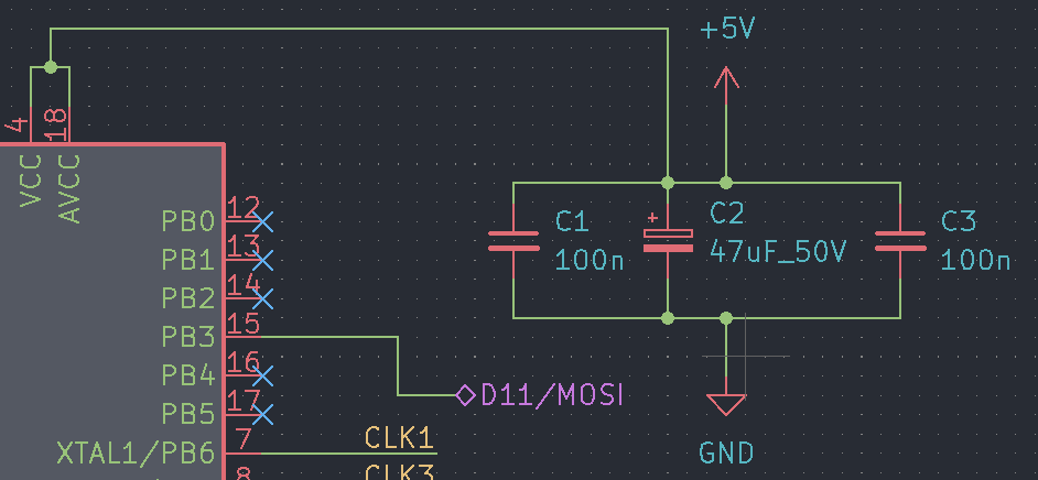
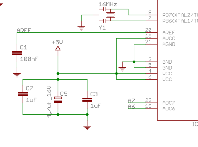
I have a question about some capacitor values. I'm building, as part of my project, an Arduino with an ATmega328. For some reasons, in my design I have capacitors of 47 k that allow me to construct 100 μF and others of 100 nF. That's fine, in order to keep using fewer different capacitors, I want to know if this change that I made is correct.

In the original design this is the construction in the Arduino's original schematic:

enter image description here

And I made this change:

enter image description here

I think it's a filter control of the power signal to try to mitigate the problems with spikes, but I don't know how critical it is, that is, if it's not too critical to support these changes (with critical I mean, how strict must be the values).

I see this other question: Changing decoupling capacitor values

I know the duty of them, my question is about the "grade" of difference, because I'm changing from 1 μF and 4.7 μF to 100 nF and 47 μF, and I don't know if that scale of change is too much.

\$\endgroup\$

3 Answers 3

4
\$\begingroup\$

Experience shows that nothing good ever comes from deviating from manufacturer recommendations... is your original schematic actually a manufacturer recommendation though, and not just some random Arduino board?

Anyway, these are large enough to act as "bulk" caps at some extent, to counter small surges. It's custom for MCUs to have a cap between 4u7F to 10uF somewhere on the main supply. I have no idea why you want to go up to 47uF - in that case I'd probably place the larger bulk cap directly after the voltage regulator (since the whole 5V net would benefit from it) and keep a smaller one on the MCU Vcc pin.

The exact value of the MCU Vcc cap is however unlikely to be critical, and you certainly don't have to use an expensive cap with polarity there. Sprinkling 3 caps with very similar values also seems needlessly expensive and I can't think of any good reason for that, unless there are multiple pins far from each other. In that case one cap per pin would be recommended, but since the pins are called 4 and 6, this doesn't seem to be the case.

I'd pick a single 6u8F X5R 10V ceramic cap instead. Tolerance etc is not critical at all. Should be available from 0603 or larger.

This doesn't rule out a decoupling cap of 100nF in parallel on the same pin though, if that's what the manufacturer actually recommends. Filtering fast spikes and filtering surges are somewhat different purposes.

\$\endgroup\$
1
  • \$\begingroup\$ Humm, I got it, I've strayed too far of manufacter desing.... I'll change that 47uF capacitor while I try to make the BOM shorter. Thanks a lot \$\endgroup\$
    – jairoG
    Commented Oct 1, 2022 at 10:15
4
\$\begingroup\$

There is no bypass cap value that is theoretically required.

For example, AVR hardware design considerations suggests a value of 100nF.

So of course you can change the value within reason.

It is unknown why your example has 1uF but it can be just as good value as 100nF.

\$\endgroup\$
1
  • \$\begingroup\$ I understand... Perfect, but My desing is the black background, and original 1uF, but thats fine, I undertand the answer, basically try it. I thought that it could be fine but i wanted to you if was fine. \$\endgroup\$
    – jairoG
    Commented Sep 30, 2022 at 9:00
0
\$\begingroup\$

A very common combination is a 10uF tantalum or ceramic in parallel with a 100nF ceramic. Each type offers different filtering capabilities in terms of the frequencies they are able to absorb. Tantalum caps, for instance, possess low ESR, which is important at high-frequencies filtering as it dissipates less heat. As a general rule, the most important parameter is the type of dielectric (as someone already mentioned). XR5 or XR7 dielectrics have great properties for EMI rejection and ripple filtering.

\$\endgroup\$
3
  • 1
    \$\begingroup\$ Isn't the low ESR argument of tantalums a thing of the past? As in, sure they do have low ESR compared to aluminium electrolytes. But compared to ceramics... ceramics should have better ESR, better ESL, better ESR stability, doesn't come with pyrotechnical potential, doesn't cost a fortune. Am I missing something? \$\endgroup\$
    – Lundin
    Commented Sep 30, 2022 at 10:39
  • \$\begingroup\$ @Lundin yes, you are totally right. I should have clarified in my answer that the ESR goes like Ceramics << Tantalum << Eletrolytics. However, this is still relevant these days. If you see the power delivery sections from a laptop (say MacBooks, for instance) you will find that the primary type of capacitors used for filtering the output on buck/boost converters are precisely Tantalum \$\endgroup\$ Commented Sep 30, 2022 at 11:39
  • \$\begingroup\$ Yeah tantalum was the way to go until 2010 somewhere. It was the best combination where (relatively) high capacitance met low ESR. Then 1uF or even 10uF ceramics were released in 0805 or 1206, and from there these high capacitances have become available in smaller and smaller packages. As long as you don't require too high voltages. \$\endgroup\$
    – Lundin
    Commented Sep 30, 2022 at 13:00

Your Answer

By clicking “Post Your Answer”, you agree to our terms of service and acknowledge you have read our privacy policy.

Not the answer you're looking for? Browse other questions tagged or ask your own question.