10
\$\begingroup\$

This and this discuss about the 3-level DC-to-DC converter.

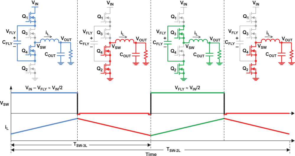
All of these are saying that the flying capacitor voltage is 1/2 VIN. However, I couldn't find any more explanation on this. Probably it's something obvious, but I have trouble seeing it.

What is the proof, assuming that all components are ideal? I understand that you may need some control circuit to balance the capacitor voltage in real life, but I want to see how it balances in the ideal case.

Enter image description here

\$\endgroup\$
0

3 Answers 3

6
+200
\$\begingroup\$

Assuming you reach the steady state operation, the average current through the inductor has to be constant. Can you see why?
The average current will have to flow through your load (R) because the capacitor does not pass DC currents. And if the current changes, the voltage at the load would change implying the steady state has not been reached.
Now calculate the change in the current in each cycle (\$T_{SW-3L}\$ in your figure). In each cycle, $$ \Delta I_{1} = \frac{V_{IN}-V_{FLY}-V_{O}}{L}T_1 - \frac{V_{O}}{L}T_2\\ \Delta I_{2} = \frac{V_{FLY}-V_{O}}{L}T_1 - \frac{V_{O}}{L}T_2 $$ Here, I have assumed ideal conditions, the duty cycles are exactly matched i.e. \$D= D_{180}\$ and that \$T_1+T_2 = T_{SW-3L}\$.
Now if we are in a steady state, the average current is constant, and hence there should be no net increment or decrement of the current in any cycle hence, $$ \Delta I_1 = \Delta I_2 = 0\\ \implies V_{IN}-V_{FLY} = V_{FLY}\\ \implies V_{FLY} = \frac{V_{IN}}{2} $$ So there you have it.
I must emphasize, this will only hold under perfectly matched conditions that are not true in practice. In practical situations, some form of feedback control would be needed to ensure that the flying capacitor has the correct voltage.

\$\endgroup\$
4
  • \$\begingroup\$ I see you have a proof which is nice but I don't quite understand why you call the expressions on the right hand side of the first two equations are average current . I think that is not average current. It's the lowest point of inductor current at the end of a cycle. \$\endgroup\$
    – emnha
    Commented Nov 25, 2022 at 11:43
  • \$\begingroup\$ @emnha You are right. You can calculate the average current and show it with that as well. But I tried to make a simpler proof and made a mistake. I have corrected it now. But as I said the main reason for the result is constant average current. \$\endgroup\$
    – sarthak
    Commented Nov 25, 2022 at 12:54
  • \$\begingroup\$ Basically, since you are decreasing the current by the same amount every cycle, the increment in the current should also be the same to keep the average constant. That is what I wanted to show in my answer. \$\endgroup\$
    – sarthak
    Commented Nov 25, 2022 at 13:01
  • \$\begingroup\$ The proof is nice. I have some more circuits with more capacitors and I'll check if I can you use to find their voltages. \$\endgroup\$
    – emnha
    Commented Nov 25, 2022 at 13:50
5
\$\begingroup\$

It might help if you looked at those diagrams as having the full Vcc applied between top and bottom, but the bottom is not grounded -- instead, Vcc has an additional capacitive divider with its middle point grounded:
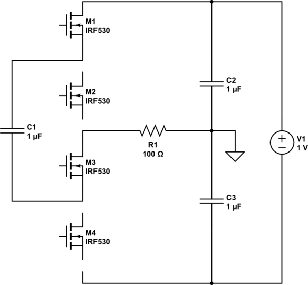
schematic

simulate this circuit – Schematic created using CircuitLab

Now it should be more clear that the voltage applied per one leg of the half-bridge is Vcc/2. I've left M2 and M4 disconnected, it's intended, to show how the connections go for the first picture in the OP: M1 and M3 are closed so the voltage across them is zero, while C1 sees the full voltage of C2, before discharging on the load. The bottom switches (M3, M4) have the negated command pulses seen by the top. The other four steps should see the transistors switching each once, not all at once, not more than one at a time (think Johnson counter). I've only recently read about these things and, as I understand it, there can be more than one way to drive these but, the effect is that the switches have reduced voltage across (halvened in this case) and the effective switching frequency is N-1 levels times the carrier. E.g. for a 3-level, N-1=2 so the effective switching frequency is twice the carrier, resulting in lower losses and reduced values for the output filter. The downside is the number of switches (and capacitors). These applications make sense for high voltage, not high current (polyphase is a better choice then).


[edit]

First, note this key quote from TI's site (emphasis added):

By maintaining the flying capacitor balance at half the input voltage, the switch node can be presented with V IN, V IN over 2, or ground. Hence the name 3-level converter.

That's one clue. Then, in case the words in the comments were not enough, below is how the schematic in the OP transforms to the one above.
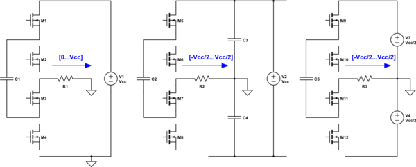
schematic

simulate this circuit

The 1st schematic to the left is the one in the OP and the load sees a voltage ranging from [0...Vcc], with a virtual modpoint at Vcc/2. If you transform this into the 2nd schematic you get the same voltage swing across the load but now, the midpoint is the actual ground, while the output can be negative. And the 3rd one is the same as the 2nd, except you're using two sources of Vcc/2, instead of only one of Vcc and two capacitors.

The reason for this transformation is to show why the flying capacitor charges at Vcc/2:

  • in the 1st one it's not immediately obvious because the load seems to take the full Vcc across it. But then it charges/discharges in a PWM fashion, so there will be an average.
  • for the 2nd and 3rd it's clear that the capacitor can only charge at Vcc/2, and then is discharged at -Vcc/2, same PWM involved.

It should be clear that the voltage across the flying capacitor can exceed, or go below Vcc/2 (also see the example in the comments) but, keeping it at Vcc/2 is optimal. This is for a buck converter, in the case of an SPWM, things change (the modulation index varies).

And, as always, you don't have to take my words for it, use a SPICE verification:
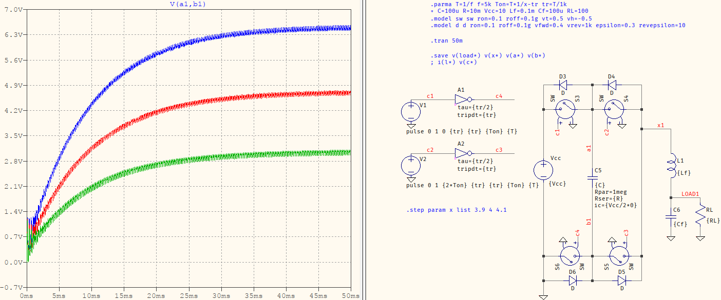
Vcc can vary

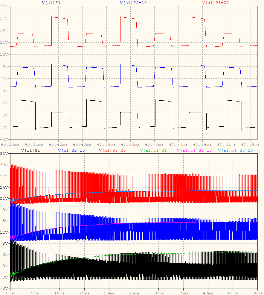
Ton is varied to be either ¼ of T, or slightly below/above. The result is that V(a1,b1) (the voltage across the flying capacitor) varies at Vcc/2, or above/below. With a balanced drive, the voltage is maintained at Vcc/2. When the output voltage varies, the duty cycle will need to vary but, even at that point, it will try to maintain a voltage of Vcc/2 or close to it. And the reason is to have the output pulse swings as even as possible:
effect of imbalance in Ton

At the top you see the voltage at the midpoint of the half-bridge. The blue trace is balanced: the pulses are closely matched in amplitude resulting in an even current through the inductor (which, as the TI video states, results in a peak current of 25% that of a regular buck converter). The black and red traces are the imbalanced ones and the effect will be higher peaks in the inductor current. At the bottom, the traces may be a bit harder to see but, they are shown as the voltage across the flying capacitor charges (see the light blue, pink, and green traces), overlayed on the waveforms of the half-bridge midpoints (all of them have some offsets for better viewing).


TLDR:

  1. The voltage across the flying capacitor is maintained at Vcc/2 because that provides the optimal output/losses/efficiency/etc
  2. The reason I showed that topology in the 1st picture was for an easier viewing of how the supply voltage charges the capacitor (direct charge from the source/capacitor, compared to the averaged Vcc).

And the reason I started with the 2nd point was because I assumed that, since the TI video (which you say you viewed) states, in clear, several times, that the voltage across the flying capacitor is maintained at Vcc/2, I didn't think that was even a problem. At any rate, now I've added that bit, too.

\$\endgroup\$
12
  • \$\begingroup\$ It makes more sense now but where would the capacitors C1, C2 from? \$\endgroup\$
    – emnha
    Commented Nov 22, 2022 at 18:09
  • \$\begingroup\$ @emnha Shameless self-quote: "instead, Vcc has an additional capacitive divider with its middle point grounded" (right in the beginning). That's the purpose of the alternate view: I am proposing another way of looking at what you have there so I am adding two capacitors to help visualize that their middle point coincides with the capacitors' middle point and with Vcc/2. If you look closely, each of those extra capacitors can be replaced by two series transistors (as if mirrored) -- in which case you'll have a bridge. It's just basic half-bridge topology, nothing special. \$\endgroup\$ Commented Nov 23, 2022 at 8:25
  • \$\begingroup\$ That does not really answer my question. You added two capacitors with same capacitance and because of the capacitive division the voltage at the midpoint is half of the input voltage. However my question is that where do the capacitors from? Are they parasitic capacitors of the transistors? Or are you just adding them as a guess whether they actually exist or not? \$\endgroup\$
    – emnha
    Commented Nov 23, 2022 at 14:02
  • 1
    \$\begingroup\$ [ ] I think you misunderstood my question. I know how it operate when you assume VCF = 1/2Vin. What I want to know is why the capacitor voltage balance to VCF = 1/2 Vin. [Edited by a moderator.] \$\endgroup\$
    – emnha
    Commented Nov 23, 2022 at 17:05
  • 1
    \$\begingroup\$ @emnha It's a clue because it's imposed, and it is so through Ton=¼ of T (in the answer, between 2nd and 3rd pics). The proof is in the picture itself, showing what a variation of Ton does to the voltage across the flying capacitor, both long and short term, and on the half-bridge midpoint (which has additional clues in the peaks of the voltages and how they vary with Ton). Sarthak's answer says exactly what I said, only with formulas. So my answer, and my comments, all answer your question. But if you don't think so, be my guest. \$\endgroup\$ Commented Nov 25, 2022 at 14:58
1
\$\begingroup\$

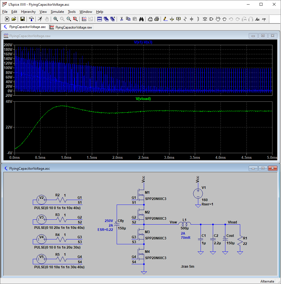
This looked like an interesting topology to simulate, so I built a version in LTspice:

LTspice simulation of a flying-capacitor converter

Green is the output voltage, totally unregulated about 36V and 2A. Blue is calculated voltage across capacitor over time. Gate sources have 1ns rise/fall and zero dead-time, but all other components include parasitics.

From this, it seems that the voltage across the capacitor varies as a function of load and pulse timing. Here it has even exceeded supply voltage. So to say it is "Vcc/2" can be misleading. It seems there is little data on this voltage because it is variable, depending on many aspects of the design.

A microcontroller-based design could prioritize keeping this voltage peak near Vcc/2 (for best efficiency) via altering the gate timings. Try it for yourself:

Version 4
SHEET 1 1224 680
WIRE 544 -64 544 -96
WIRE 896 -64 896 -96
WIRE -160 16 -176 16
WIRE -32 16 -80 16
WIRE 128 16 48 16
WIRE 144 16 128 16
WIRE 480 16 464 16
WIRE 496 16 480 16
WIRE -176 48 -176 16
WIRE 128 48 -176 48
WIRE 144 48 128 48
WIRE 480 48 368 48
WIRE 544 48 544 32
WIRE 544 48 480 48
WIRE 896 48 896 16
WIRE 544 64 544 48
WIRE -160 144 -176 144
WIRE -32 144 -80 144
WIRE 128 144 48 144
WIRE 144 144 128 144
WIRE 368 144 368 48
WIRE 480 144 464 144
WIRE 496 144 480 144
WIRE -176 176 -176 144
WIRE 128 176 -176 176
WIRE 144 176 128 176
WIRE 480 176 464 176
WIRE 544 176 544 160
WIRE 544 176 480 176
WIRE 736 176 544 176
WIRE 768 176 736 176
WIRE 912 176 848 176
WIRE 992 176 912 176
WIRE 1072 176 992 176
WIRE 1120 176 1072 176
WIRE 1168 176 1120 176
WIRE 544 192 544 176
WIRE 912 240 912 176
WIRE 992 240 992 176
WIRE 1072 240 1072 176
WIRE 1168 240 1168 176
WIRE -160 272 -176 272
WIRE -32 272 -80 272
WIRE 128 272 48 272
WIRE 144 272 128 272
WIRE 480 272 464 272
WIRE 496 272 480 272
WIRE -176 304 -176 272
WIRE 128 304 -176 304
WIRE 144 304 128 304
WIRE 368 304 368 208
WIRE 480 304 368 304
WIRE 544 304 544 288
WIRE 544 304 480 304
WIRE 544 320 544 304
WIRE 912 352 912 304
WIRE 992 352 992 304
WIRE 1072 352 1072 304
WIRE 1168 352 1168 320
WIRE -160 400 -176 400
WIRE -32 400 -80 400
WIRE 128 400 48 400
WIRE 144 400 128 400
WIRE 480 400 464 400
WIRE 496 400 480 400
WIRE -176 432 -176 400
WIRE 128 432 -176 432
WIRE 144 432 128 432
WIRE 480 432 464 432
WIRE 544 432 544 416
WIRE 544 432 480 432
WIRE 544 480 544 432
FLAG 896 48 0
FLAG 896 -96 Vcc
FLAG 544 480 0
FLAG 544 -96 Vcc
FLAG 480 16 G1
FLAG 480 48 S1
FLAG 480 144 G2
FLAG 480 176 S2
FLAG 480 272 G3
FLAG 480 304 S3
FLAG 480 400 G4
FLAG 480 432 S4
FLAG 736 176 Vsw
FLAG 1072 352 0
FLAG 1168 352 0
FLAG 1120 176 Vload
FLAG 128 16 G1
FLAG 128 48 S1
FLAG 128 144 G2
FLAG 128 176 S2
FLAG 128 272 G3
FLAG 128 304 S3
FLAG 128 400 G4
FLAG 128 432 S4
FLAG 992 352 0
FLAG 912 352 0
SYMBOL voltage 896 -80 R0
WINDOW 123 0 0 Left 0
WINDOW 39 24 124 Left 2
SYMATTR InstName V1
.SYMATTR Value 160
SYMATTR SpiceLine Rser=1
SYMBOL sym\\nmos 496 -64 R0
SYMATTR InstName M1
SYMATTR Value SPP20N60C3
SYMBOL sym\\nmos 496 64 R0
SYMATTR InstName M2
SYMATTR Value SPP20N60C3
SYMBOL sym\\nmos 496 192 R0
SYMATTR InstName M3
SYMATTR Value SPP20N60C3
SYMBOL sym\\nmos 496 320 R0
SYMATTR InstName M4
SYMATTR Value SPP20N60C3
SYMBOL ind 752 192 R270
WINDOW 0 32 56 VTop 2
WINDOW 3 5 56 VBottom 2
SYMATTR InstName L1
SYMATTR Value 500µ
SYMATTR SpiceLine Ipk=2 Rser=0.07 Rpar=8000 Cpar=10p mfg="Gowanda" pn="894AT5003V"
SYMBOL polcap 352 144 R0
WINDOW 3 24 56 Left 2
SYMATTR InstName Cfly
SYMATTR Value 150µ
SYMATTR Description Capacitor
SYMATTR Type cap
SYMATTR SpiceLine V=250 Irms=1.87 Rser=0.2235 Lser=11.8n mfg="Würth Elektronik" pn="860241181007 WCAP-AT1H 18x31,5" type="Al electrolytic"
SYMBOL polcap 1056 240 R0
WINDOW 3 24 56 Left 2
SYMATTR InstName Cout
SYMATTR Value 150µ
SYMATTR Description Capacitor
SYMATTR Type cap
SYMATTR SpiceLine V=250 Irms=1.87 Rser=0.2235 Lser=11.8n mfg="Würth Elektronik" pn="860241181007 WCAP-AT1H 18x31,5" type="Al electrolytic"
SYMBOL res 1152 224 R0
SYMATTR InstName R1
SYMATTR Value 22
SYMBOL voltage -64 16 R90
WINDOW 0 -15 70 VLeft 2
WINDOW 3 51 104 VLeft 2
WINDOW 123 0 0 Left 0
WINDOW 39 0 0 Left 0
SYMATTR InstName V2
SYMATTR Value PULSE(0 10 0 1n 1n 10u 40u)
SYMBOL res 64 0 R90
WINDOW 0 0 80 VBottom 2
WINDOW 3 1 31 VBottom 2
SYMATTR InstName R2
SYMATTR Value 1
SYMBOL voltage -64 144 R90
WINDOW 0 -15 70 VLeft 2
WINDOW 3 51 104 VLeft 2
WINDOW 123 0 0 Left 0
WINDOW 39 0 0 Left 0
SYMATTR InstName V3
SYMATTR Value PULSE(0 10 20u 1n 1n 10u 40u)
SYMBOL res 64 128 R90
WINDOW 0 0 80 VBottom 2
WINDOW 3 1 31 VBottom 2
SYMATTR InstName R3
SYMATTR Value 1
SYMBOL voltage -64 272 R90
WINDOW 0 -15 70 VLeft 2
WINDOW 3 51 104 VLeft 2
WINDOW 123 0 0 Left 0
WINDOW 39 0 0 Left 0
SYMATTR InstName V4
SYMATTR Value PULSE(0 10 0 1n 1n 20u 30u)
SYMBOL res 64 256 R90
WINDOW 0 0 80 VBottom 2
WINDOW 3 1 31 VBottom 2
SYMATTR InstName R4
SYMATTR Value 1
SYMBOL voltage -64 400 R90
WINDOW 0 -15 70 VLeft 2
WINDOW 3 51 104 VLeft 2
WINDOW 123 0 0 Left 0
WINDOW 39 0 0 Left 0
SYMATTR InstName V5
SYMATTR Value PULSE(0 10 10u 1n 1n 30u 40u)
SYMBOL res 64 384 R90
WINDOW 0 0 80 VBottom 2
WINDOW 3 1 31 VBottom 2
SYMATTR InstName R5
SYMATTR Value 1
SYMBOL cap 976 240 R0
SYMATTR InstName C2
SYMATTR Value 2.2µ
SYMATTR SpiceLine V=100 Irms=0 Rser=0.008 Lser=900p mfg="Würth Elektronik" pn="885382209002 WCAP-CSST 1210" type="X7R"
SYMBOL cap 896 240 R0
SYMATTR InstName C1
SYMATTR Value 1µ
SYMATTR SpiceLine V=100 Irms=0 Rser=0.0053 Lser=651p mfg="Würth Elektronik" pn="885012209069 WCAP-CSGP 1210" type="X7R"
TEXT 784 232 Left 2 ;2A\n70mR
TEXT 344 152 Right 2 ;250V\n2A\nESR=0.22
TEXT 782 448 Left 2 !.tran 5m
\$\endgroup\$

Your Answer

By clicking “Post Your Answer”, you agree to our terms of service and acknowledge you have read our privacy policy.

Not the answer you're looking for? Browse other questions tagged or ask your own question.