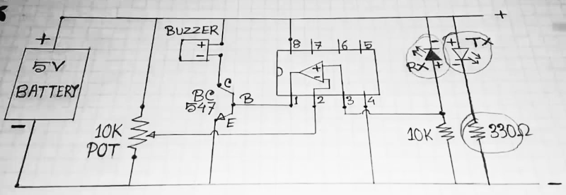
In other words, will the device work in the opposite way than it should?
I realize that this is not your schematic, and you are stuck with its imperfections. Another one is the lack of reference designators, and the opamp needs a decoupling capacitor. But let's move on to answering your question . . .
The circuit as shown will work. Ignoring the + and - indications, both diode bodies are connected correctly as shown.
When there is no reflection to couple IR energy from the TX part to the RX part, current through the RX part will be so low that the voltage across the 10K resistor is lower than the voltage at the wiper of the sensitivity adjustment pot. In this condition, the opamp output is saturated low, and the driver transistor is off. This is how the circuit ignores ambient IR energy.
When reflection happens, current through the RX device increases, the voltage at the opamp non-inverting input increases until it is above the voltage at the inverting input, and the opamp output saturates high. This turns on the driver transistor.
To further improve the circuit, add hysteresis around the opamp to improve its immunity to changing ambient IR levels. Also, the unused opamp in the package should have its inputs terminated so it doesn't break into oscillation.
The LM358 output stage has build-in current limiting, and is rated to drive a short circuit continuously. The circuit relies on this current limiting to protect both the opamp and the driver transistor. This is very bad design practice.
Add a 4.7 K resistor between the opamp output pin 1 and the transistor base.
Add a 0.1 uF capacitor across the opamp power pins. Keep the capacitor leads as short as possible.


