0
\$\begingroup\$

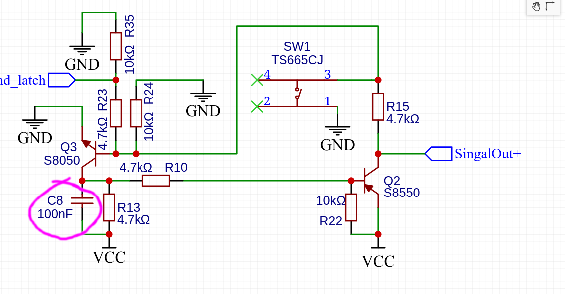
I have a very basic NPN - PNP latching circuit:
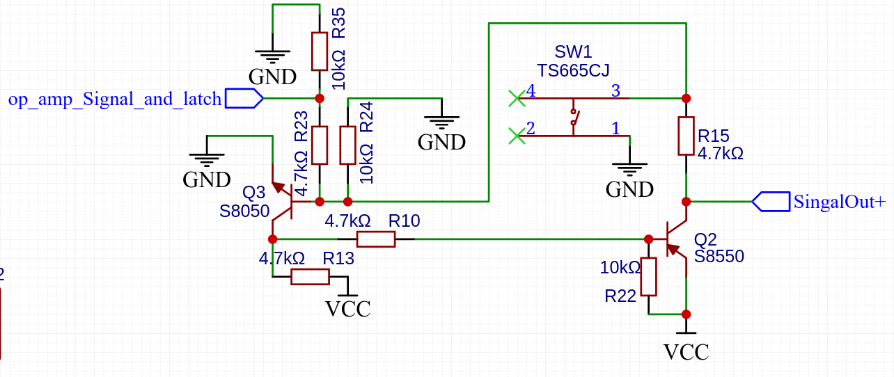
enter image description here [Sorry for the upside down image]

The latch initially is off, and when the op_amp_Signal_and_latch turns on, the transistors should latch and there should be output to SignalOut+ which drives other transistors.

I just made the latch part in a breadboard with a 10uF snubber capacitor connected to +ve and ground.

It works great until I turn on the fan, the light (even incandescent bulb) or the AC, or pretty much anything in the room. Doing so, latches the transistors, and I've to press the button to release the latch.

Sometimes touching any part of the circuit also latches the circuit.

I've connected an oscilloscope to see the noise that turns on the transistor, but unfortunately I was not able to catch any extra voltage induced by the EMI in the base and collector of the transistors.

My idea was to add a RC Delay circuit to delay latch signal, but with enough EMI it might charge up the capacitor and latch the circuit, just a bit delayed. But it will eventually happen.

So false triggering defeats the purpose of having the latch. When making PCB I'll surely take care of the copper area connected to the ground and also use SMD components which might stick to the board well and reduce the EMI effect due to the grounded copper area.

But I don't like the circuit. How do I get rid of the false triggering?

\$\endgroup\$
0

1 Answer 1

2
\$\begingroup\$

Looks like all I needed is a 0.1uF capacitor I had lying around and connect them between the signal capacitor (Q3 in question) and +ve:

enter image description here

Now:

  1. It doesn't falsely trigger no matter how many times I touch the circuit
  2. No effect from EMI

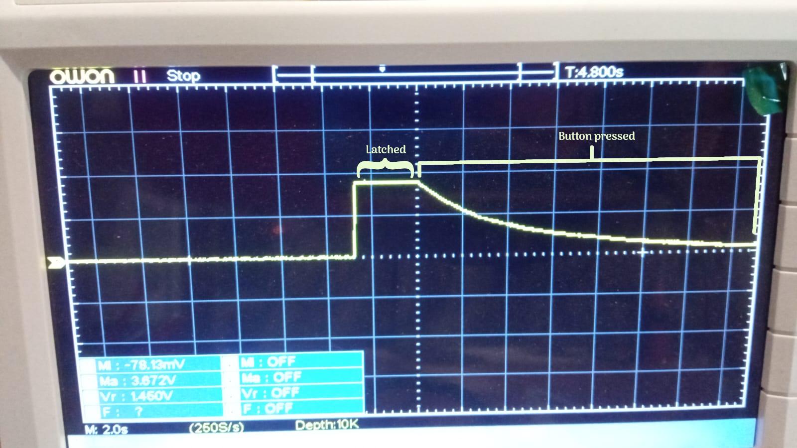
As mentioned by @Tim Williams in comment, the bigger the value of the capacitor the longer you have to press the button and also longer activation time.

For example, I replaced the 100nF capacitor with a 1000uF capacitor, and here's what happens:

enter image description here

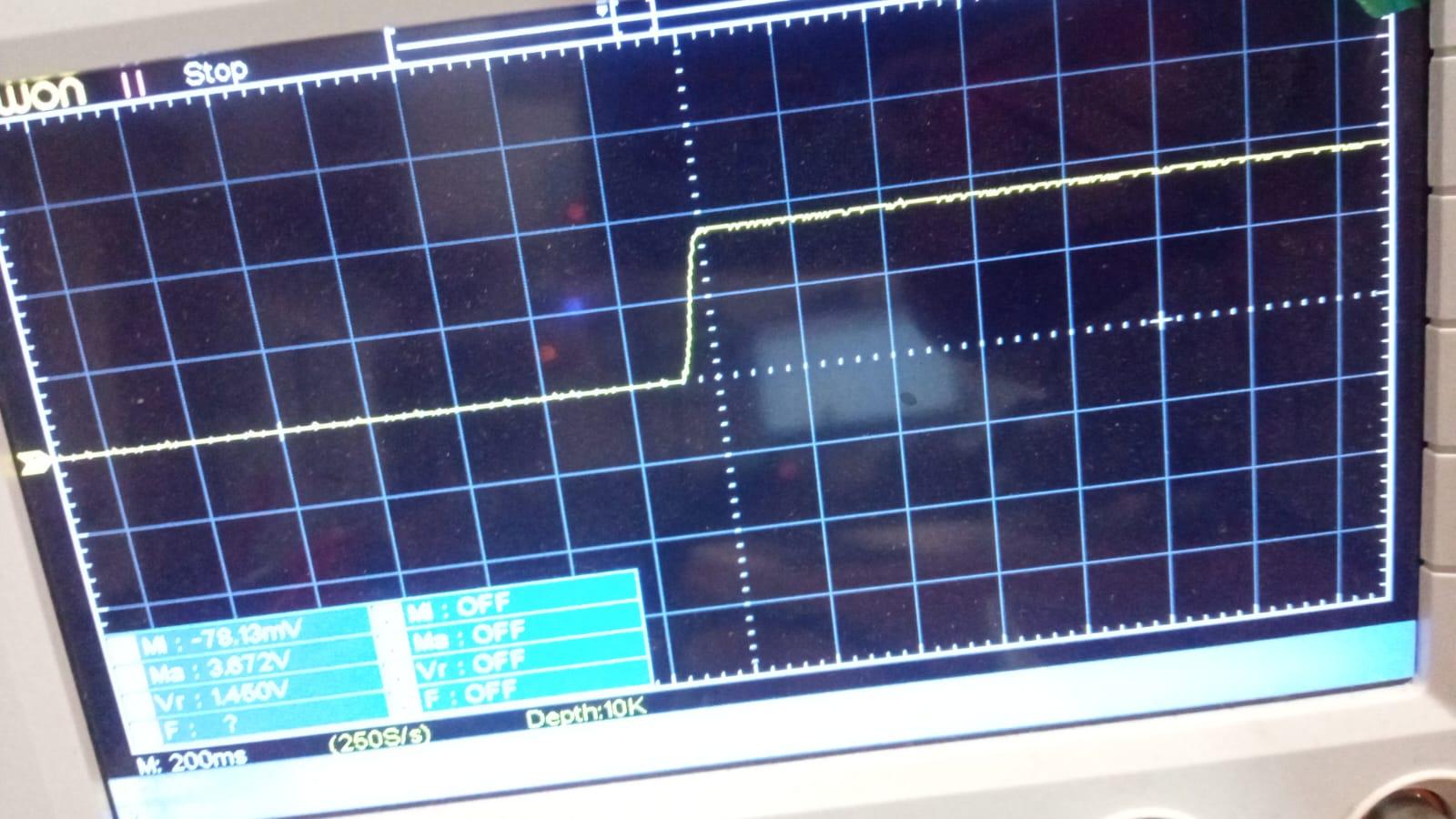
The activation time is also higher:

enter image description here

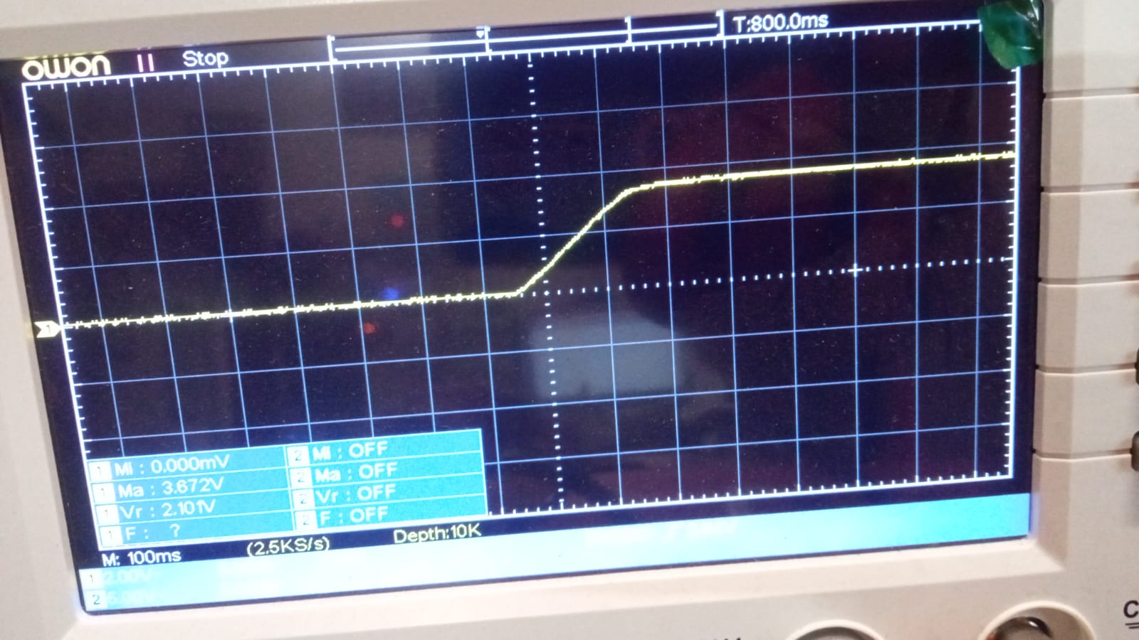
With a bigger capacitor (4700uF):

enter image description here

So for now the 100nF capacitor works perfectly and I ran the circuit for 12 hours straight without getting it latched.

\$\endgroup\$
1
  • 2
    \$\begingroup\$ Note that this solution increases the minimum pulse width required from op_amp_Signal_and_latch. (And SW1, but that's pretty much a given from a user-actuated switch.) If this signal is maintained for more than long enough anyway, no problem. \$\endgroup\$ Commented Mar 24, 2023 at 21:54

Your Answer

By clicking “Post Your Answer”, you agree to our terms of service and acknowledge you have read our privacy policy.

Not the answer you're looking for? Browse other questions tagged or ask your own question.