0
\$\begingroup\$

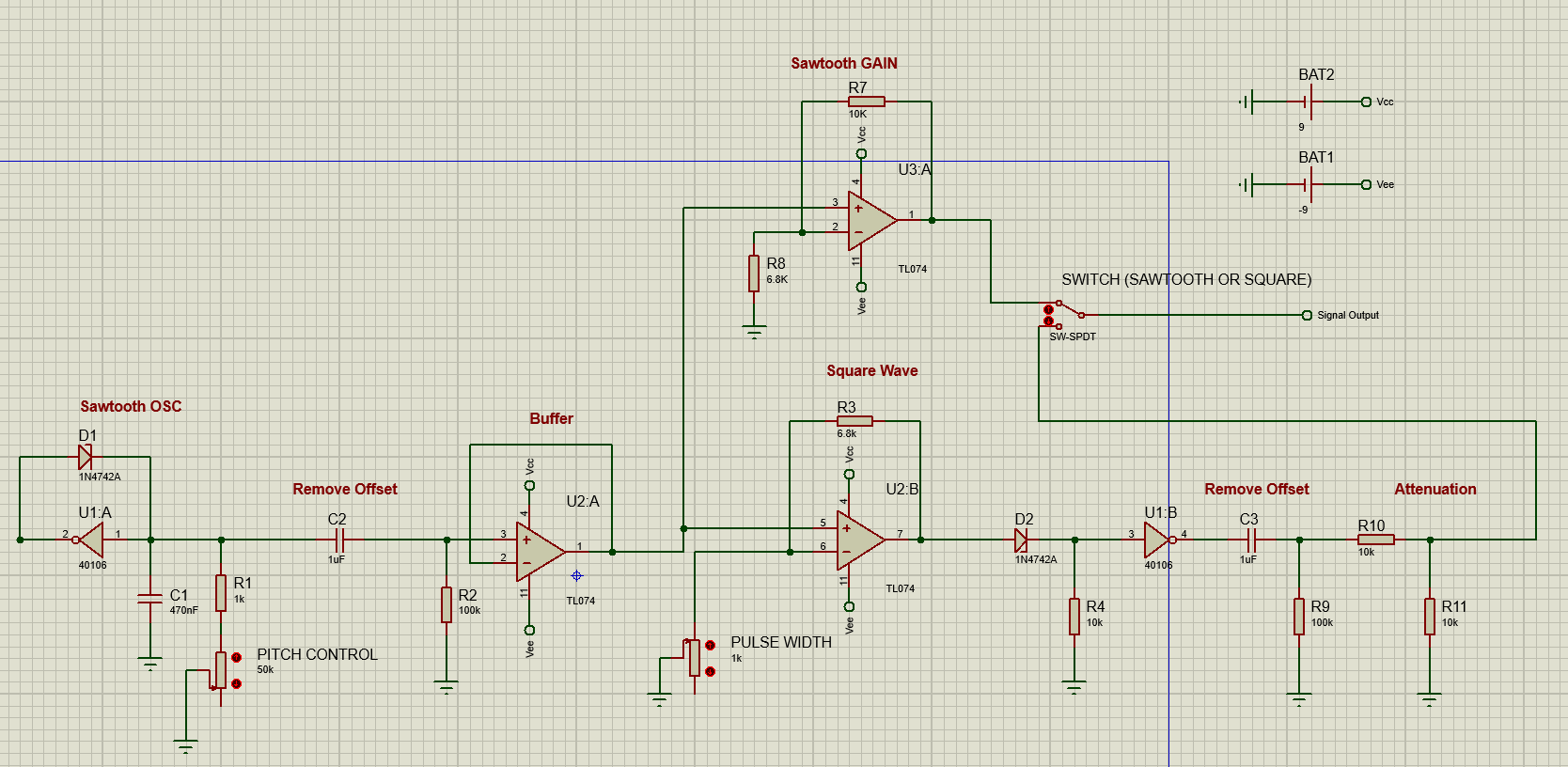
I’m doing a project of four oscillators where each one allows switching between a sawtooth or square waveform. The diagram that I attach is the corresponding one for a single oscillator, each one has a potentiometer of 50k ohms that allows to modify the pitch of every single one. However I'm having problems trying to create a "master potenciometer" that allow to change the pitch from all the oscillators at the same time. The output of the signals of the four oscillators are being processed into an summing operational amplifier in order to function as a "Mixer".

I try adding a single 10k potentiometer in series with each 50k potentiometer. However, although the 10k potentiometer allows you to modify the pitch of all oscillators at the same time. The problem arises when I modify with the pitch of a single one oscillator with its corresponding 50k potenciometer, it changes the pitch of the others when the idea is to only change the pitch of only that single oscillator without modifying the others. enter image description here.
\$\endgroup\$
3
  • 1
    \$\begingroup\$ One straightforward way would be a 4-gang potentiometer, which is to say, 4 potentiometers connected to the same knob \$\endgroup\$ Commented Apr 5, 2023 at 19:21
  • \$\begingroup\$ I think you have discovered why oscillators for commercial modular synthesizers use voltage control rather than resistance. \$\endgroup\$
    – Theodore
    Commented Apr 5, 2023 at 19:23
  • 1
    \$\begingroup\$ Another idea is to use a transistor as a variable resistor and control 4 transistors from the same gate/base voltage. (I don't remember whether BJTs or MOSFETs are better for this, nor how they should be biased) \$\endgroup\$ Commented Apr 5, 2023 at 19:24

1 Answer 1

1
\$\begingroup\$

The problem with a single 10k pot in series with the group of 50k pots is that the point where they join is not 'stiff', is not a low impedance like ground. This means that adjusting any of the 50k pots will, as you've found, move that point and so alter the other oscillators.

The oscillator configuration you have chosen is amenable (to some extent) to voltage control, as well as resistance control, which allows you to have a low impedance solution.

schematic

simulate this circuit – Schematic created using CircuitLab

R1 will at best be a limited trim on the oscillators' frequencies, as you will have to keep Vref well below the charge voltage from your oscillator UA1. The control law will also be 'whatever you get'. However, the opamp buffer output is a low impedance point, and so will isolate the adjustment of R2 from R3 and any of the other oscillator controls.

Ideally, you would use voltage controlled oscillators. The type you have chosen is very prone to frequency variation with voltage and temperature variations. If you run the synth from a power supply, that may well have stable enough rails that Vref can simply be a resistive divider down to the pot. If from a battery, then you will probably want to use a voltage reference for stability.

\$\endgroup\$
1
  • \$\begingroup\$ ¡thank you very much! It worked. \$\endgroup\$
    – Zlmanuel87
    Commented Apr 5, 2023 at 20:35

Your Answer

By clicking “Post Your Answer”, you agree to our terms of service and acknowledge you have read our privacy policy.

Not the answer you're looking for? Browse other questions tagged or ask your own question.