0
\$\begingroup\$

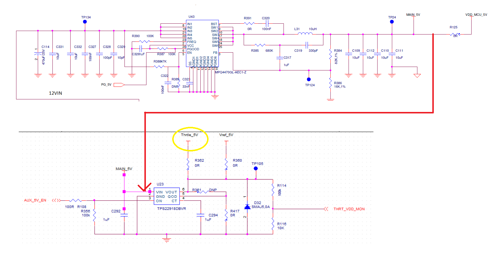
I have a buck converter which converters 12V to 5V,3A. The output of this buck converter is going to a load switch and from the load switch it is going to a connector.

What we observed is that after 3 or 4 months the output of the buck converter is becoming 5.5V in some of the boards.

May I know why it is happening? Is this a layout issue or any stability issue?

enter image description here

U43 is present in the bottom side and U23 is present in TOP side of the Board. U23 output (Thrtle_5V) is going to the connector.

This is a 6 layer board.

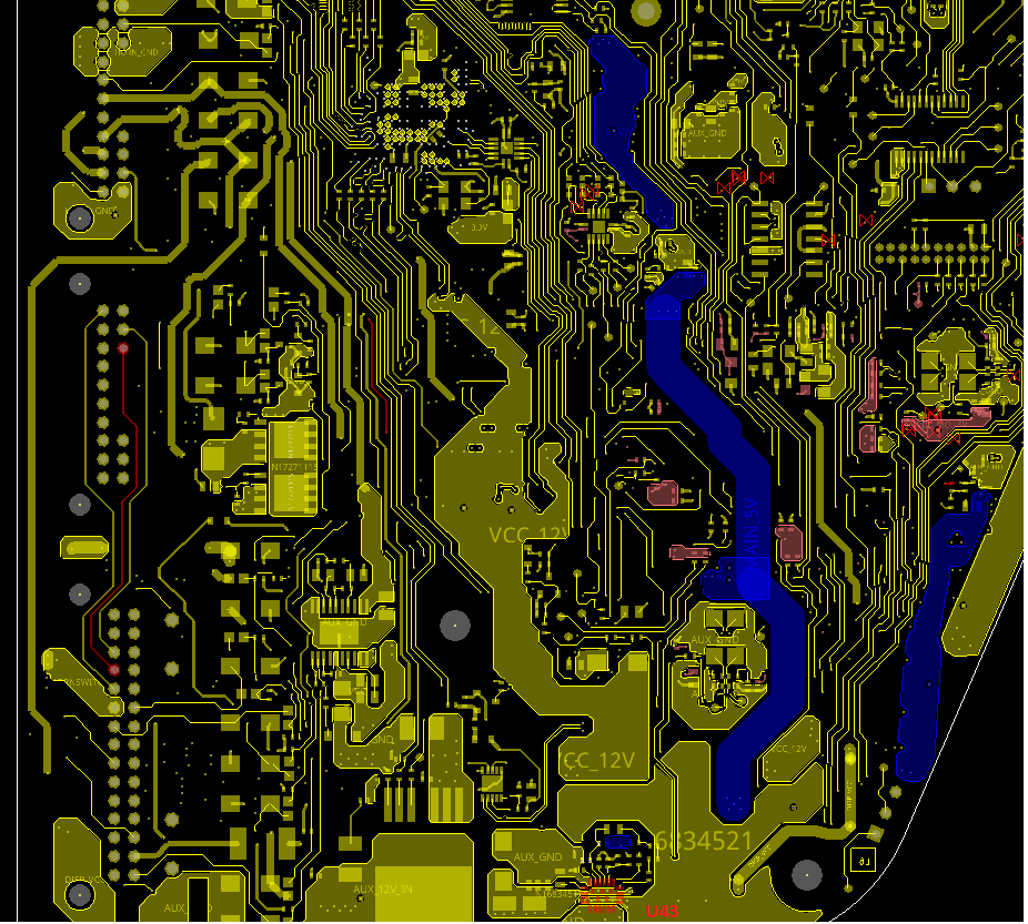
Below is the Layout of Bottom. Blue color shows MAIN_5V and the red shows Thrtle_5V

enter image description here

Layer 5 is a GND plane.

Layer 4 is shown below. It has different power islands.

enter image description here

Layer 3 is power plane. Layer 2 is GND plane.

Top layer is given below.

enter image description here

Datasheet of U43 is given below.

https://www.monolithicpower.com/en/documentview/productdocument/index/version/2/document_type/Datasheet/lang/en/sku/MPQ4470GL-AEC1-Z/document_id/2273/

Datasheet of U23 is given below.

https://www.ti.com/lit/ds/symlink/tps22918.pdf?ts=1682503065746&ref_url=https%253A%252F%252Fwww.ti.com%252Fproduct%252FTPS22918%252Fpart-details%252FTPS22918DBVR%253Futm_source%253Dgoogle%2526utm_medium%253Dcpc%2526utm_campaign%253Docb-tistore-promo-app_opn_en-cpc-storeic-google-in%2526utm_content%253DDevice%2526ds_k%253DTPS22918DBVR%2526DCM%253Dyes%2526gclid%253DCjwKCAjwl6OiBhA2EiwAuUwWZZjq3keEvbLieRLGPZpWl74bDSd2SHmLhVlV4MdiHItALS_evK7cBBoCW9kQAvD_BwE%2526gclsrc%253Daw.ds

\$\endgroup\$
5
  • \$\begingroup\$ Please provide data sheet links to U43 and L31 and explain where and how you are making the voltage measurement that appears to be problematic. \$\endgroup\$
    – Andy aka
    Commented Apr 27, 2023 at 8:00
  • \$\begingroup\$ @Andyaka,datasheets are added.We are measuring the voltage at R362 other side shown in yellow circle \$\endgroup\$
    – Confused
    Commented Apr 27, 2023 at 8:22
  • \$\begingroup\$ Read my comment more carefully please. Also, the main 5 volts <-- was that voltage OK? \$\endgroup\$
    – Andy aka
    Commented Apr 27, 2023 at 8:37
  • \$\begingroup\$ @Andyaka,No mains 5V is also not proper.We are measuring using DMM \$\endgroup\$
    – Confused
    Commented Apr 27, 2023 at 8:42
  • \$\begingroup\$ How does the waveforms look? Are there any electrolytic capacitors present? If you scope the FB pin on an offending unit, what do you measure? \$\endgroup\$
    – winny
    Commented Apr 27, 2023 at 12:07

1 Answer 1

1
\$\begingroup\$

We create devices for indoor and outdoor environments, but we use a surface protection spray (with silicon ... PCB conformal coating) from a British company after all the components are mounted and the PCB cleaned.

You have sometimes dust in the environment and a little bit of dust find his way onto the board and this will cause a lower resistance between the feedback pin of the StepDown converter and GND. Or possibly some flux is still there and causes the problem.

You should measure the resistance between the Feedback pin and ground. The problem is, that you could destroy the evidence if you change something on the PCB. There is possibly some liquid or aggressive flux under U43 or maybe directly around R386.

I would remove R384 (82k resistor) and then measure the resistance between Feedback and GND.

  • Then clean the PCB (between the two resistors) with Isopropanol and test again. (if this solved the problem, then there was some dirt between the resistors and you need a dust protection)
  • At the end remove the chip U43 with hot air, clean everything and use new solder-paste to solder the chip on the PCB. (if this solved the problem, then there was something under the chip and this was a error during the production)
\$\endgroup\$
3
  • 1
    \$\begingroup\$ 'I would remove R384 (82k resistor) and then measure the resistance between Feedback and GND' May What is the expected value and what is the inference from this resistance measurements \$\endgroup\$
    – Confused
    Commented Apr 27, 2023 at 8:26
  • 1
    \$\begingroup\$ There are many more possibilities, "broken" solder connection, but the resistance is only increased a little bit. Normally I expect that the resistance would change because of a changing temperature or switch between 0 Ohm and infinite. But we had an unusual error-pictures because of errors during the production process. If you have the same error on several PCBs, then it could be an error during the production. \$\endgroup\$
    – MikroPower
    Commented Apr 27, 2023 at 9:28
  • \$\begingroup\$ In this board also full conformal coating is present. \$\endgroup\$
    – Confused
    Commented Apr 27, 2023 at 11:31

Your Answer

By clicking “Post Your Answer”, you agree to our terms of service and acknowledge you have read our privacy policy.

Not the answer you're looking for? Browse other questions tagged or ask your own question.