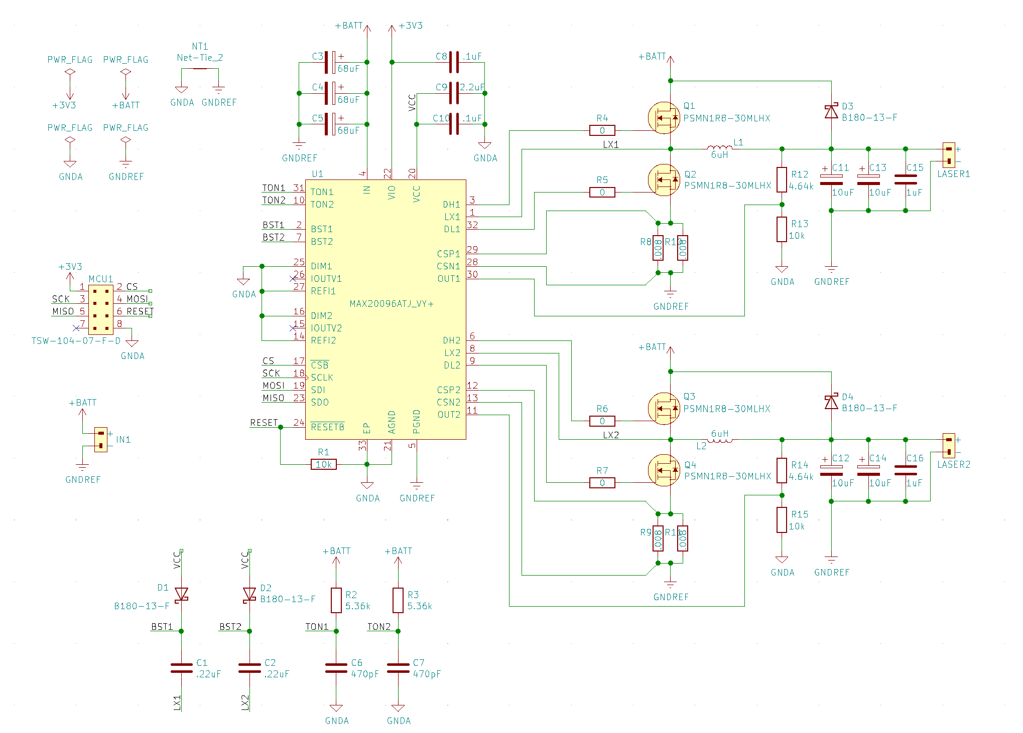
I am building a dual high current buck driver for driving two fiber coupled laser diode arrays. This is my second attempt at a board -- my first attempt had excessive ringing due to the board layout (documented in this earlier question from me). The design parameters are:
- Vin: 8v nominal
- Vout: 2v - 4v (constant current supply)
- Current set: 50A
- Input ripple: 1%
- Output ripple: 1%
- Switching frequency: 500kHz
- Control IC is a MAX20096
The schematic:
I received some great advice in my previous post and I have tried to apply it all to this new layout. I've also found a great set of articles on buck converter PCB Layout I tried to closely follow as well as a careful study of the PCB Layout for the MAX20096 evaluation board. The layout is now:
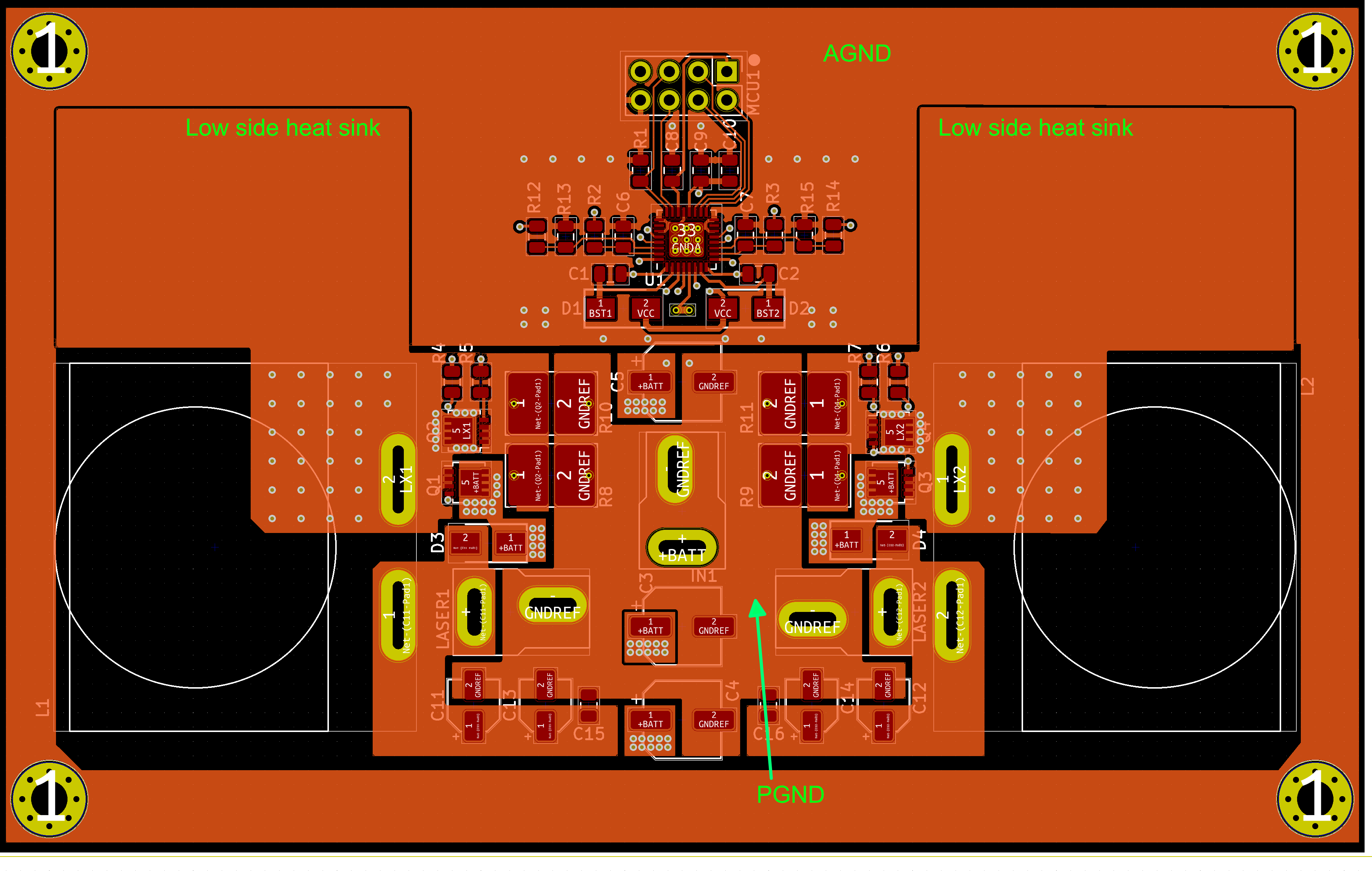
- 4 layers. Inner layer 1 is a dedicated ground layer.
- High current ground is separate from analog ground. They are tied together at a single point very close to the control IC.
- Tried to reduce current loop length as much as possible.
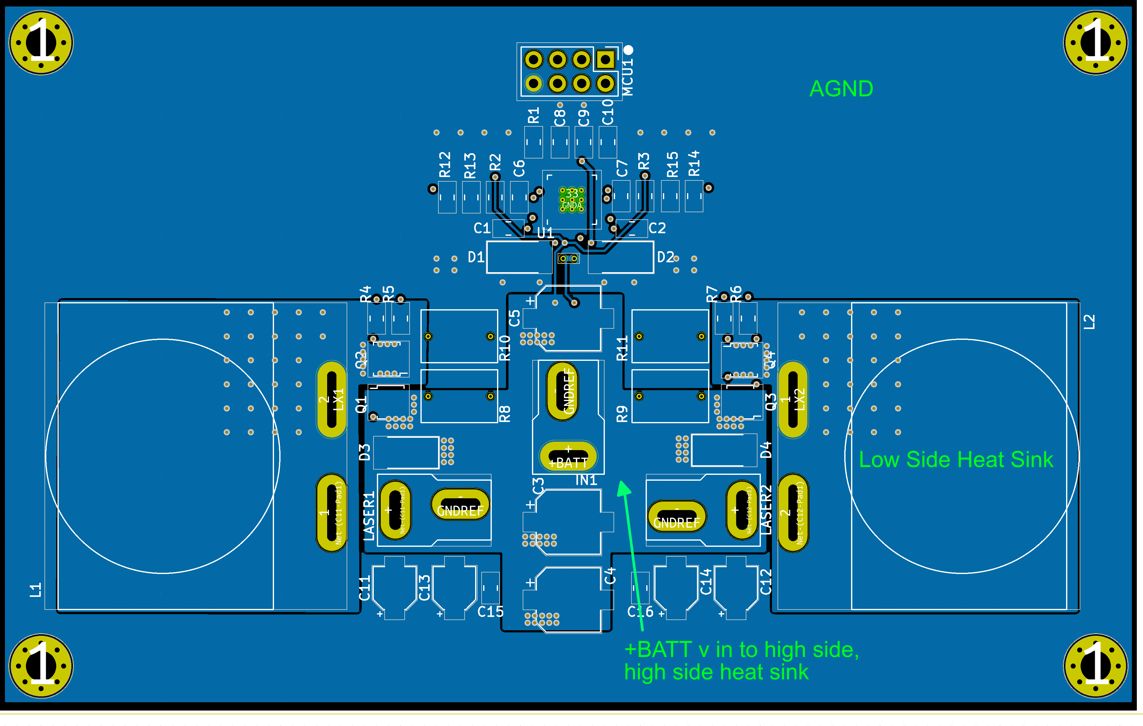
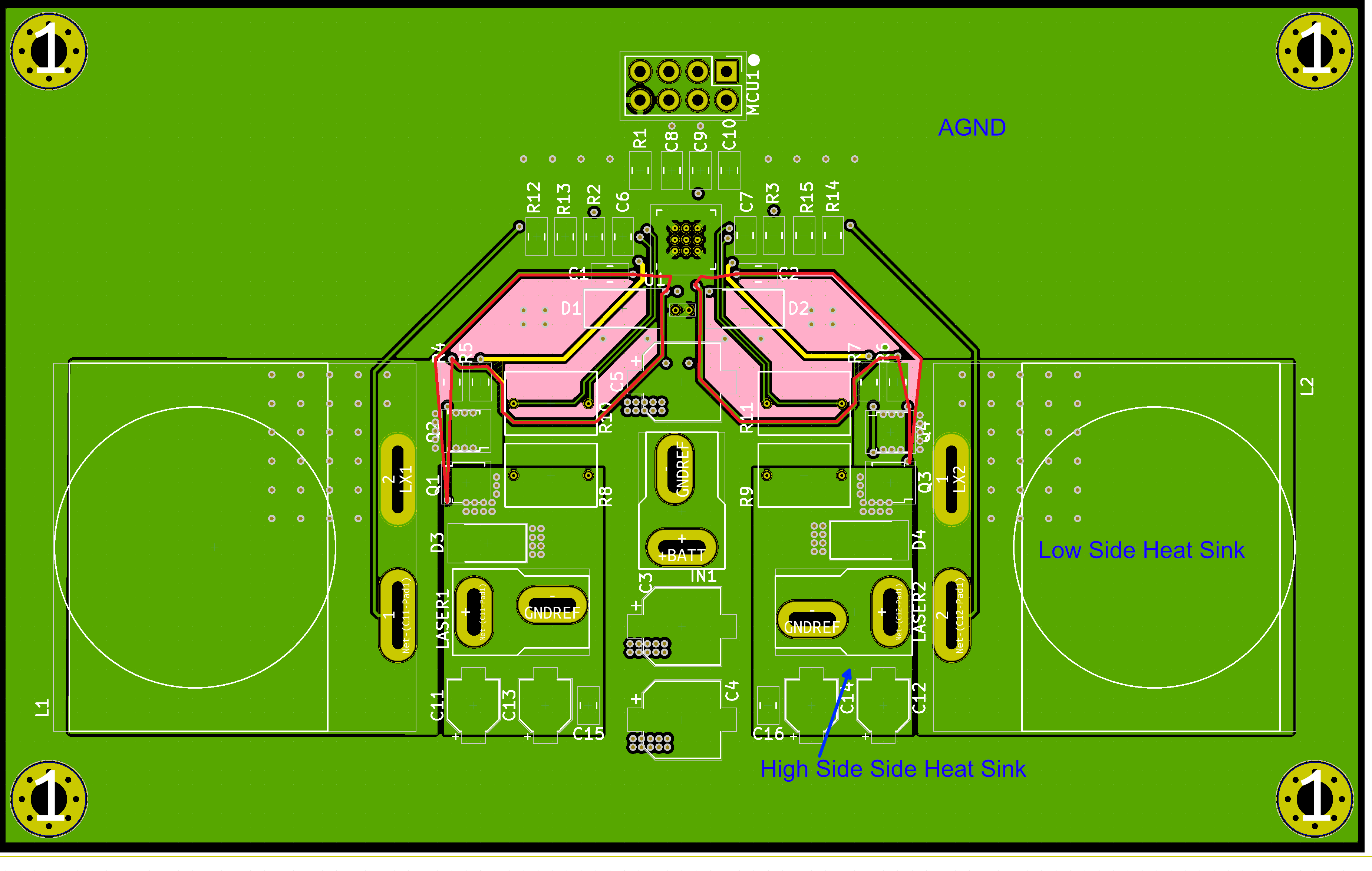
- Current sense is now done via Kelvin connection routed using differential pairs.
Here are the layouts for each of the layers:
Inner Layer 1 (dedicated ground plane)
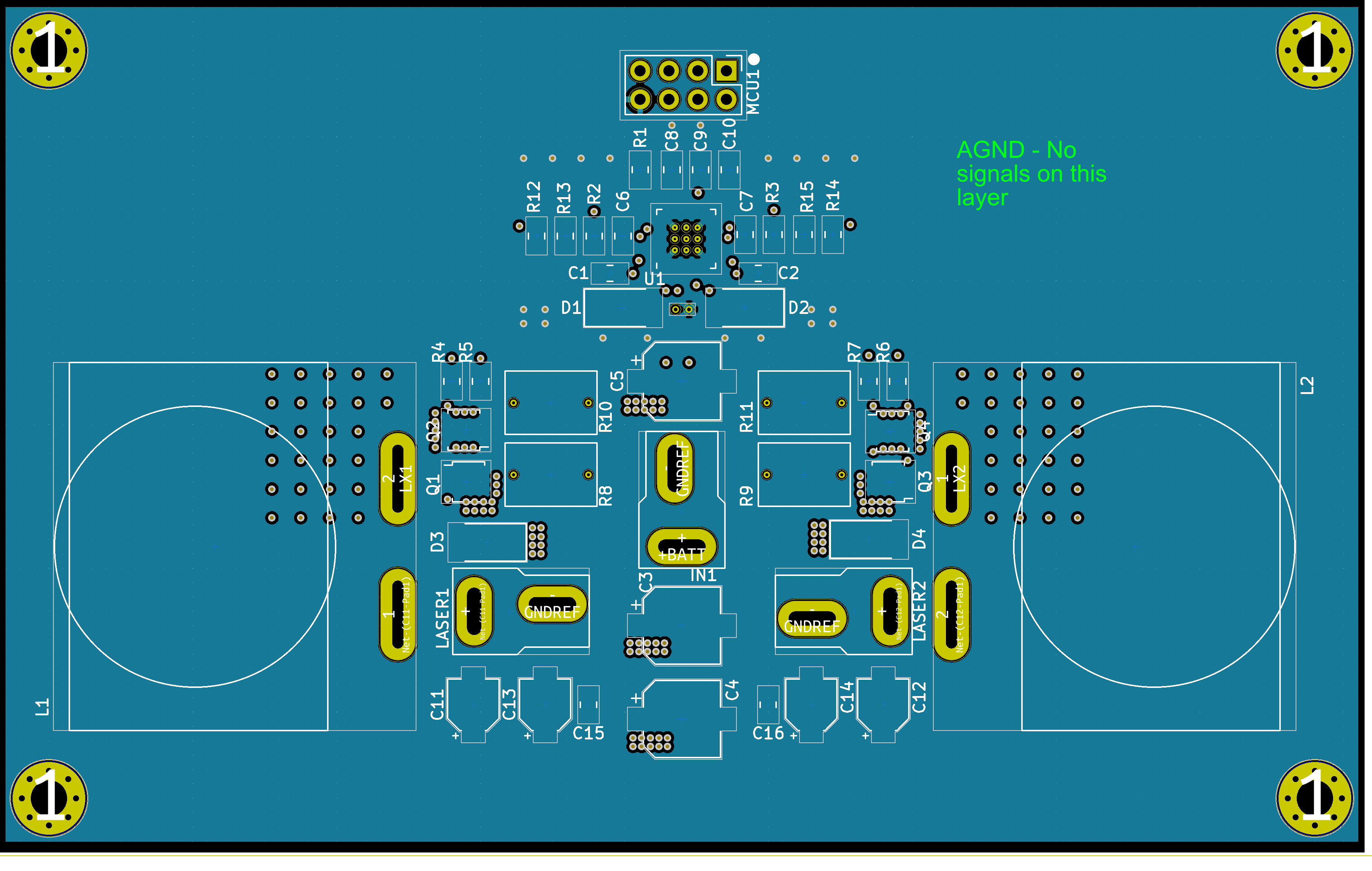
Inner Layer 2 (sense, gate drive)

Thanks in advance for any advice.

