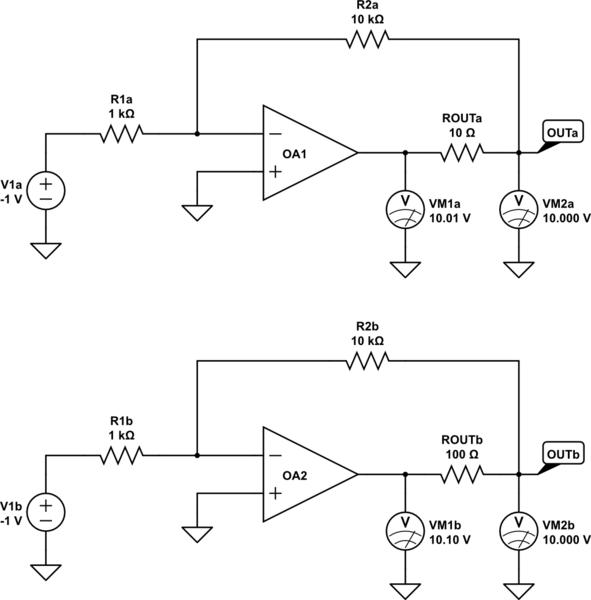
If we artificially introduce an impedance in series with an op-amp's output, and we take feedback from and measure the output after that resistance, we will see how negative feedback compensates for this extra impedance, and produces the correct output regardless:

simulate this circuit – Schematic created using CircuitLab
The outputs from these op-amps are considered to be OUTa and OUTb, and output resistance is being modelled by ROUTa and ROUTb. Remembering that since these resistances are representing impedance inside the IC, their left ends are usually inaccessible from outside, but with this model I am able to show the potential at this "hidden" node, as measured by VM1a and VM1b.
I have set gain to \$-\frac{10k}{1k}=-10\$, so that with an input of -1V we would expect the outputs of an unmodified op-amp to be +10V. You might think that the presence of ROUT would cause the output to deviate significantly from the ideal of +10V, but remarkably, even though we have increased the output impedance of the op-amps significantly, both circuits are still producing exactly +10V at their surrogate outputs, as shown by VM2.
This is because of negative feedback, which causes the op-amp to adjust its output to whatever value is necessary to equalise the potentials at its inverting and non-inverting inputs. It doesn't matter how much current you draw from the output, or how much voltage is dropped across ROUT, the op-amp still does whatever it has to do to bring those to inputs to the same potential.
You can see how the op-amp compensates for the voltage drop across ROUT, by raising its output slightly higher than the required 10V output. Notice how "internally" the op-amps are producing slightly more than 10V, shown on VM1.
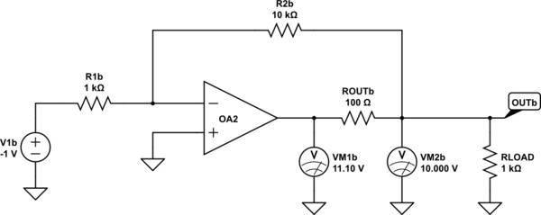
There's more. If I place a load on the surrogate output OUTb, say a 1kΩ resistor which would draw \$\frac{10V}{1k\Omega}=10mA\$, look what happens to the potential of OUTb:

simulate this circuit
Absolutely nothing happens. Somehow, the output is still exactly +10V, in spite of there being 10mA more current flowing through ROUTb. Remember, all the op-amp is doing here is adjusting its output to ensure that its two inputs have the same potential. Considering that the only way that can this condition of equality can be true, is if node OUTb is at exactly +10V, this makes sense. If node OUTb was lower, then the op-amp would act to raise the output, until that equilibrium is achieved.
You can see on VM1b that this is exactly what happened. The voltage there has risen to +11.1V, a rise of exactly enough to bring OUTb to +10V, which is exactly the potential necessary to equalise the op-amp's two inputs. All this happens in spite of our attempt to "weaken" the op-amp with ROUT, and to demand more current with RLOAD. The response of the op-amp (due to negative feedback) is simply to "pull harder"!
To get back to your question, how to measure the amplifier's output impedance, perhaps you don't need to. We have increased current output by adding RLOAD, and that had no effect on output voltage. That's another way of saying that output impedance is zero.
In practice, it is only near zero, because op-amps are never ideal. If you want to measure that near-zero output impedance, you'll need some pretty precise measurement equipment, because any change in output potential as current varies, is going to be tiny.
If you are interested in measuring the output impedance of the op-amp, then you must do so with the loop open, with no negative feedback. This requires you to bias the two inputs very very precisely, to get the output somewhere near the mid-point of the power supply potentials, and then load the output while monitoring output potential change. This is hard to do, as any temperature change or even the slightest input potential change will cause the output to quickly diverge from where you initially put it.


