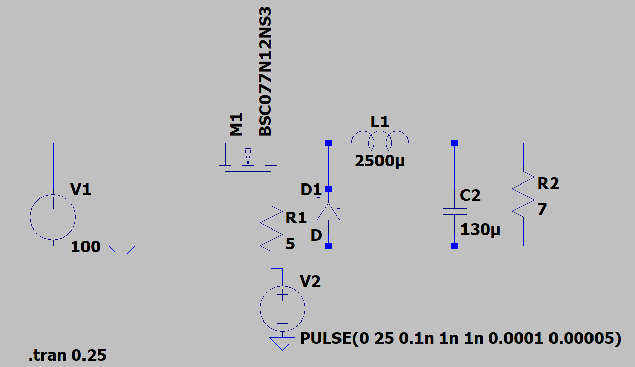
I have been trying to understand the working of buck converter (without the use of a dedicated IC). So, I used LTspice to test a circuit on the parameters:
- Vin: 100 V
- Vout: 50 V
- Freq.: 10 kHz
- I: 5 A
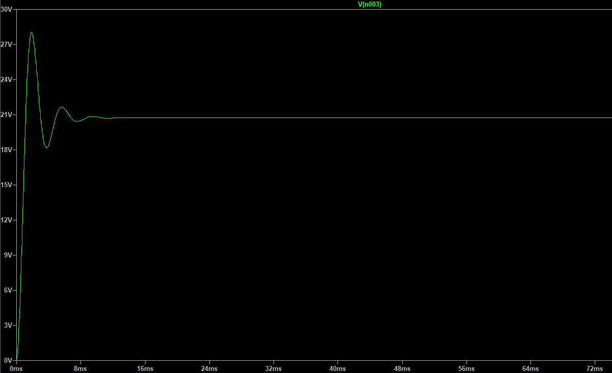
I went through the TI's guide to calculate the values (C2 is 125 uF), but upon simulating the circuit I can't seem to get it to give proper Vout. As seen in the graph, it gives around 20.7 V as output; far less than 50 V. I read some of the stack questions on the buck, but they all deviated a little or more from my problem. Moreover, the Vout changes when I either change the gate pulse voltage and/or the load resistor. After setting the gate voltage to 120 V, the output comes near the 50 V threshold (but not exact), and I am unable to understand why the output changes with the load resistor or the pulse voltage. The rest seem to work properly, but can't seem to understand the Vout issue.
Answer update:
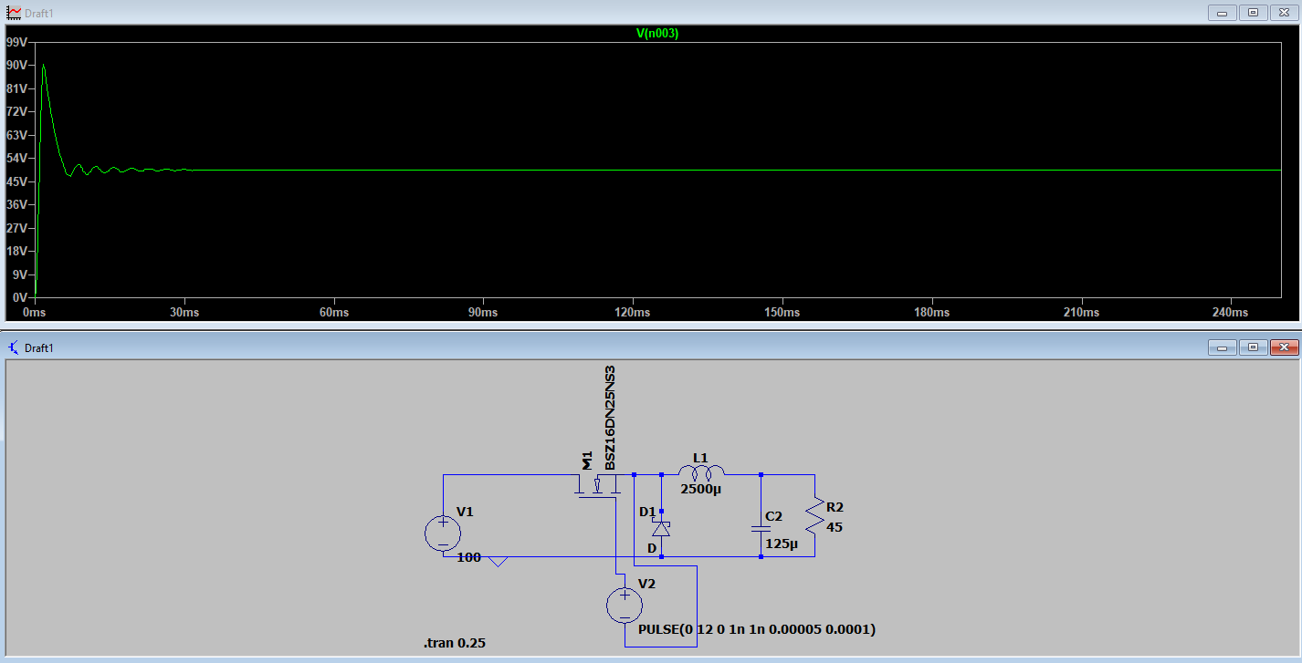
When the negative of the pulse driver is connected with the source, and a pulse of 12V is provided to the FET, the voltage on the Gate is 111V (approx.). As the Vs rises when the Gate turns on and Rds decreases, the equivalent voltage on gate becomes Vg = Vs + Pulse voltage. Here is the updated circuit with output. The Vout is stable now.


