0
\$\begingroup\$

I need some help with the below circuit.

Circuit:

3-phase AC circuit (3 phases and neutral). 120deg phase shift between the 3.

I need to provide a signal to the Microcontroller.

If one of the phases is missing, or most importantly, if phase difference is greater than 120deg between any of the two phases, then I need to convey this information to the MCU.

Initially, I thought of using an OR gate IC and giving the output of the gate to the MCU. But using the OR gate, it is not possible to convey the phase difference information to the MCU.

\$\endgroup\$
6
  • \$\begingroup\$ Basicly you need three zero-crossing or polarity detectors then coney that information to the microcontroller and have the microcontroller compare the timing to get phase angle \$\endgroup\$ Commented Aug 8, 2023 at 4:00
  • \$\begingroup\$ This is the real world. Phase angle is never exactly 120.000 degrees, one of them will be over, perhaps pick a different threshold. \$\endgroup\$ Commented Aug 8, 2023 at 4:02
  • \$\begingroup\$ @JasenСлаваУкраїні, sure. Could you give an idea on how to identify the phase difference between the any two phases if the thresholds are different? \$\endgroup\$
    – Freshman
    Commented Aug 8, 2023 at 4:07
  • \$\begingroup\$ use timers in the microcontroller to measure the time difference, \$\endgroup\$ Commented Aug 8, 2023 at 4:08
  • 2
    \$\begingroup\$ connect it to another mcu \$\endgroup\$ Commented Aug 8, 2023 at 11:17

2 Answers 2

2
\$\begingroup\$

One single two-state signal to detect phase problems of a three-phase system:

Use one comparator each to compare each phase to zero and generate the exclusive or of the comparator output signals.
Each comparator output changes state whenever the potential difference at its inputs changes sign, one input being tied to the reference potential ("ground"), whenever the input signal "crosses zero".
An ExOr's output (equivalently, an ExNOr's output) changes state whenever an odd number of inputs changes state; in particular, when one input changes state.
An MCU can monitor the time between state changes, there should be six for every mains period.
Evenly spaced when the phase difference is 120° or 2π/3.

Here's a sketch at falstad.com - try changing one of the phase angles.

Electrical safety may mandate to isolate signal processing from "the three phases".

\$\endgroup\$
6
  • \$\begingroup\$ Thank you for the answer. Can you please explain a bit more or an image of the circuit will help me understand better? \$\endgroup\$
    – Freshman
    Commented Aug 8, 2023 at 6:49
  • \$\begingroup\$ Thank you for the simulation. Could you please write a couple of lines to understand the working of the circuit, please? \$\endgroup\$
    – Freshman
    Commented Aug 8, 2023 at 15:32
  • \$\begingroup\$ Thank you for the answer. Really appreciate the explanation. I have 2 last questions. 1. When one of the 3- phase input is left floating, i.e, the inverting terminal is unconnected to the 3-phase input. In that case, the output will still be the same as when all 3-phases are working fine. In this case, what can be done? 2. Could you please tell me how to do the isolation? Some suggestion on this, please? \$\endgroup\$
    – Freshman
    Commented Aug 9, 2023 at 6:44
  • \$\begingroup\$ In this improved falstad setup (finally got it to show 3 phases so one can see "zero crossing"), move one of the sources to the left to disconnect it. To transfer something electrical to an isolated level, convert it to a different form of energy. In power distribution, magnetic fields are used in isolating transformers. For signalling, optocouplers are more common; transferring comparator outputs offers more flexibility than just parity (ExOr output). \$\endgroup\$
    – greybeard
    Commented Aug 9, 2023 at 7:12
  • \$\begingroup\$ Thank you. So, the non-inverting terminal's resistor has to connected to neutral of the 3-phase & the output of the comparator or more so the output of the OR gate should be referenced to the PCB digital/MCU ground, am I correct? \$\endgroup\$
    – Freshman
    Commented Aug 9, 2023 at 8:08
3
\$\begingroup\$

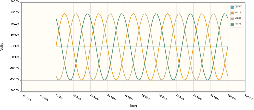
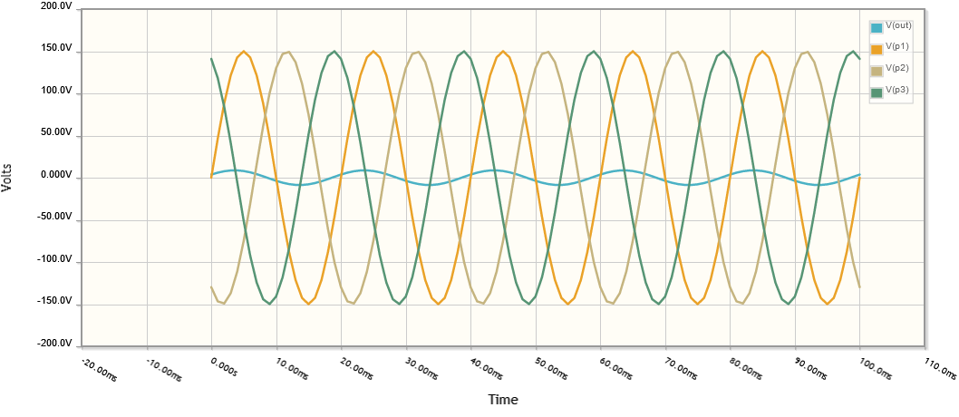
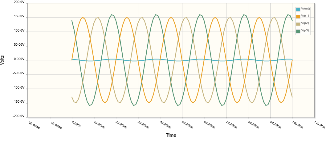
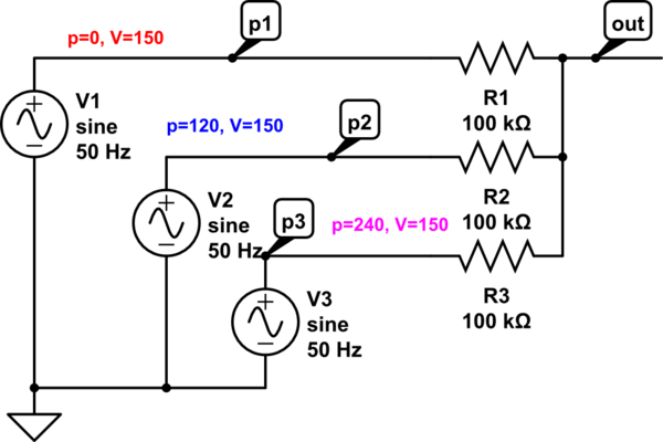
If the voltages on each phase are equal, this will give zero volts output if the phases are 0, 120, and 240 degrees.

schematic

simulate this circuit – Schematic created using CircuitLab

Balanced voltages and phase angles: balanced voltages and phase angles

Voltages with unbalanced phase p1=0, p2=120, p3=250 p1=0, p2=120, p3=250

Voltages with unbalanced amplitude p1=0, p2=120, p3=240, V(p3)=160 p1=0, p2=120, p3=240, V(p3)=160

\$\endgroup\$
2
  • \$\begingroup\$ Thank you for the answer. What happens if the voltage varies by some amount say +/-10V? 2. Also, Is the ground of the signals, neutral AC? Or a digital ground of the MCU? \$\endgroup\$
    – Freshman
    Commented Aug 8, 2023 at 6:48
  • \$\begingroup\$ Sorry - captions added. \$\endgroup\$
    – PStechPaul
    Commented Aug 11, 2023 at 18:52

Your Answer

By clicking “Post Your Answer”, you agree to our terms of service and acknowledge you have read our privacy policy.

Not the answer you're looking for? Browse other questions tagged or ask your own question.