0
\$\begingroup\$

I've searched this forum for the past few days and I didn't find any solutions or problems similar to mine.

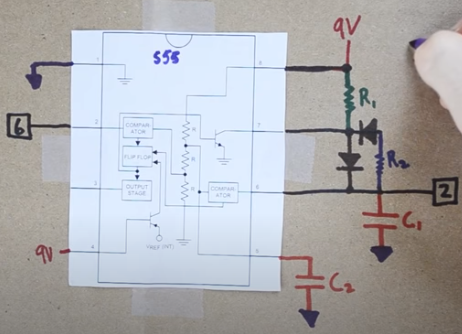
I'm working with a ne555 in astable mode with a configuration that, theoretically, should give me a duty cycle of 50% by using 2 identical resistors. I started using 1 digital potentiometer (the mcp41010) in order to have different duty cycles, but when I used the same resistance as the normal resistor the duty cycle wasn't 50%. With the multimeter I had seen the resistance value and they where different from what the resistor and the potentiometer should have been. I've decided to use 2 normal 4,7 kohm resistors to do some tries, but when I measured them the values they assumed were strange. When I put the multimeter to a scale of 20k ohm the values are 11k for one and for the other 14k, when I use a scale of 2M ohm, one resistor measured 800k ohm and the other 1.1M ohm. When I use a scale of 200 ohm one measures 60 ohm and the other doesn't show any data, so I'm confused and I don't really know if I used the multimeter in a wrong way.

The circuit I'm using was taken by a video: https://www.youtube.com/watch?v=8Z7kTCSZG5E&t=3s&ab_channel=SkinnyR%26D

The only difference is that I'm using 5 V and not 9 V.

enter image description here

\$\endgroup\$
7
  • \$\begingroup\$ How precise do you want the 50%? Is it okay at 52%? 55%? Or? \$\endgroup\$ Commented Aug 24, 2023 at 12:59
  • 2
    \$\begingroup\$ Are you trying to measure the resistors while they're in the circuit? \$\endgroup\$
    – hobbs
    Commented Aug 24, 2023 at 13:01
  • \$\begingroup\$ Yeah the resistor were in the circuit \$\endgroup\$
    – gag05
    Commented Aug 24, 2023 at 13:11
  • \$\begingroup\$ i need this circuit to controll a motor, so the closer to 50% the better \$\endgroup\$
    – gag05
    Commented Aug 24, 2023 at 13:14
  • 1
    \$\begingroup\$ Even if flip-flop is used, any cycle-to-cycle timing difference will make the duty to not be 50%. You need to define how much there can be jitter. \$\endgroup\$
    – Justme
    Commented Aug 24, 2023 at 13:25

4 Answers 4

2
\$\begingroup\$

When you're measuring a resistor in circuit and it reads considerably higher than the value it's supposed to be as yours are showing, it's probably because there is some voltage in the circuit. This could be from measuring with power supplied to the circuit (don't do that) or it could be voltage from the charge on some capacitors.

An ohmmeter measures resistance by forcing a current through it and then reading the voltage across it, knowing the current and voltage it can now find the resistance (basic Ohm's Law, R=E/I). If there is another source of voltage to the resistor the meter will read that, and give you a higher than normal reading. If there are capacitors in the circuit the current from the meter can charge them and give a higher reading.

Readings that are much lower than expected can be caused by other resistances in parallel, semiconductor junctions being biased into conduction by the meter current, or a voltage in the circuit that is the reverse polarity of what the meter expects, cancelling out some of the voltage the meter current would cause.

In some cases you can get a good resistance reading in circuit, but generally not. Better to disconnect one end of the resistor and measure it that way.

\$\endgroup\$
1
  • 1
    \$\begingroup\$ Measuring resistance higher then the actual value caused by only a capacitor seems unlikely to me. It would have to be the range changing and that value would stabilize quite quickly to the right one. Unless the measurement is changing, capacitors won't affect much an ohm meter. Batteries and power supply will definitely do. \$\endgroup\$
    – Julien
    Commented Aug 24, 2023 at 15:04
1
\$\begingroup\$

Measuring resistor in circuit cannot be done for multiple reason. Here is three previous post that had the same issue as you. Reference 1 Reference 2 Reference 3. Any measurement of resistance made with a DMM will be invalid since the semiconductor will sink or source some current. You need to remove the resistance from circuit to measure it.

EDIT: Regardless on the measurement technique, potentiometer aren't ideal resistance. In DC they might present themselves as a resistor, but they can have a lot of parasitic inductance and capacitance. Therefore, the "resistance" you measure in DC is not the same as the "resistance" you measure at 1MHz (for example). To measure your impedance at your frequency of operation, you should use an LCR meter instead of an ohm meter.

Since most people don't have an LCR meter at their hand, what you can do is to use an oscilloscope probe and measure the amplitude during operation and tune with it. Of course, the impedance of the probe will affect slightly the tuning process but if you use a good probe, you should get close to what you want.

\$\endgroup\$
7
  • \$\begingroup\$ I understand, but even measuring the components not connected the pontetiometer has the same resistance as the resistor, but the result is different than using two identical resistor, So if u can help with this I will be very thankful. \$\endgroup\$
    – gag05
    Commented Aug 24, 2023 at 14:45
  • \$\begingroup\$ Are you saying that when you measure the value of the potentiometer, alone it match the value of your resistors, alone, you don't get the same duty cycle? \$\endgroup\$
    – Julien
    Commented Aug 24, 2023 at 14:46
  • 1
    \$\begingroup\$ yeah exactly, like if I use two resistors at 4,7k i get a duty cycle, but if i use a 4,7k resistor and the potentiometer set to 4,7k i get a different duty cycle. \$\endgroup\$
    – gag05
    Commented Aug 24, 2023 at 14:52
  • \$\begingroup\$ I edited the answer to add on that. \$\endgroup\$
    – Julien
    Commented Aug 24, 2023 at 14:57
  • 1
    \$\begingroup\$ @gag05 Oh, that changes things a lot actually. Are you sure you're operating within the limits of the digital potentiometer? They usually can't handle very much current and are limited to very low voltages. \$\endgroup\$
    – Hearth
    Commented Aug 24, 2023 at 15:39
0
\$\begingroup\$

As others have mentioned, measuring resistors in circuit generally just doesn't work. It works in special circumstances, and yours isn't one.

What you care about is the output signal. Measure the duty cycle of that. You don't really care all that much about what the absolute resistor values are - only about what's on the output.

Your requirements relate to outputs - the implementation can be a black box and as long as it does what you won't you don't care much, right?

And if you already have a digital potentiometer, presumably controlled by an MCU, you may as well use an MCU timer to generate the signal in a much more straightforward fashion.

Why are you using a 555 to begin with? What is the final application this will be in? Can't you use, say, a crystal or ceramic resonator and an oscillator+divider chip? A good starting point may be a CD4060. It'll allow you to use fairly manageable component values, oscillate at a higher frequency, then divide the output to what you want. All in one chip. There are other chips like it of course, but 4060 already performs better than a 555 I think.

\$\endgroup\$
0
\$\begingroup\$

In the datasheet for the CMOS version of the 555 (LMC555, etc.), there is a circuit for a 50/50 astable oscillator. The circuit does not produce the same result with a bipolar 555 because that part has a very asymmetrical output impedance. It can discharge the timing capacitor much faster than it can charge it. The CMOS output stage is better for this. Although it cannot supply as much current as the bipolar part, its source and sink output currents are much better balanced.

Page 16:

https://www.ti.com/lit/ds/symlink/lmc555.pdf?ts=1692880281118&ref_url=https%253A%252F%252Fwww.ti.com%252Fproduct%252FLMC555

\$\endgroup\$

Your Answer

By clicking “Post Your Answer”, you agree to our terms of service and acknowledge you have read our privacy policy.

Not the answer you're looking for? Browse other questions tagged or ask your own question.