1
\$\begingroup\$

I have a simple circuit 9v connected to 3K resistor coneected to a wire. On this wire, I have two LED's connected in parallel, both leading straight to ground.

When I check insert my multimeter between the positive and resistor I get around 2.54 mA.

When I insert my multimeter between LED 1 and Ground, I get around 1.12

When I insert my multimeter between LED 2 and Ground, I get around 1.06

I'm off by around 30-40mA.

Is this acceptable and/or normal OR is multimeter broken?

I already checked the fuses, and they're not broken, as far as continuity checking is concerned.

I also replaced the batteries.

Update:

The discrepancy seems to be less when I use resistors in place of LEDs. Does the multimeter change shunt resistor when using an LED?

when using LEDs in parallel, my current is off by 20-40% if I will base it on the source current and divide that by number of branches.

but when I use resistors in place of LED, my current is off by less than 5%

Is it simply the shunt resistor or is my LED doing something I'm not aware of?

\$\endgroup\$
2
  • \$\begingroup\$ What is the accuracy and burden voltage/shunt resistance of your multimeter? Considere these and it will work out just fine most likely. \$\endgroup\$
    – PlasmaHH
    Commented Sep 16, 2015 at 10:01
  • \$\begingroup\$ I checked my manual. It says plus minus 1.5% + 3 digits. I have no idea what + 3 digits mean. \$\endgroup\$
    – user27847
    Commented Sep 16, 2015 at 10:10

2 Answers 2

2
\$\begingroup\$

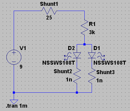
Let me try to explain it without much math and physics. For the sake of the principle, let us assume that the multimeter uses 25Ω shunt resistance (not unreasonable for a 40mA range), everything is perfect and the LEDs are dropping 2.7V. Then we can use the following LTspice simulation to illustrate what is happening:

enter image description here

With setting the shunt resistors to 1nΩ in simulation (basically off) we can determine a perfectly equal 1.0487mA per LED (it is a perfect simulation after all), thus a total of 2.097mA.

Let us now see what happens when we put the Shunt1 to 25Ω: The voltage drop across it reads 52mV which corresponds to 2.08mA. Already not quite what the simulated perfect value is. But wait, there is more. Let us set Shunt2 to 25Ω resistance and measure the voltage drop over it. It will read 22.98mV or .919mA only!

Why is that so? Well, since we have a simulation here, we can poke around and look at the "real" values, and see that through the other diode in that configuration, there is a total of 1.175mA flowing. There is our "missing" current. In the measurement situation you have created a different circuit than the one you were trying to characterize, thus you can not compare those too. Do the calculation for the above circuit where Shunt1 is 0 and Shunt2 is 25Ω, and you will see that the voltages and currents are distributed differently.

Now what you can do is to either buy some measurement equipment with much lower burden voltage, or you can figure out the shunt resistor size used in your multimeter, place it at the position of Shunt3 when you measure Shunt2, and with only minimal impact on the overall current flow (assuming 25Ω is in the right ballpark) you can measure things more properly now since the current won't get "redirected".

Btw. this is also the reason why you measure different values for different current ranges: your meter simply uses differently sized shunt resistors there.

\$\endgroup\$
1
  • \$\begingroup\$ Thank you. I will just accept 30mA discrepancy as part of my meter. \$\endgroup\$
    – user27847
    Commented Sep 16, 2015 at 12:51
1
\$\begingroup\$

You are off by about 0.36mA rather than 30 to 40 mA.

What multimeter are you using?

What is almost definitely occurring is the meter is loading the circuit. This is a well known phenomenon and can be corrected after the measurement if you know the details of the ammeter part of your multimeter.

Update

I looked at the user manual, and there are two current measurement ports on the meter you are using. As you are measuring below 4mA, try that range (if you are not already doing so.

The two setups are designed to minimise error based on measurement range.

HTH

\$\endgroup\$
2
  • \$\begingroup\$ Hi, Thank you.I'm using an Extech EX330. \$\endgroup\$
    – user27847
    Commented Sep 16, 2015 at 10:06
  • \$\begingroup\$ Read the website you linked. Really helped me out. Thank you very much! \$\endgroup\$
    – user27847
    Commented Sep 16, 2015 at 13:26

Your Answer

By clicking “Post Your Answer”, you agree to our terms of service and acknowledge you have read our privacy policy.

Not the answer you're looking for? Browse other questions tagged or ask your own question.