3
\$\begingroup\$

I am looking for a 3-legged component that can be used as a switch as an alternative to an NMOS transistor. My circuit currently looks the following: -
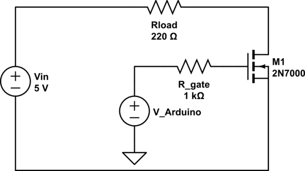
schematic

simulate this circuit – Schematic created using CircuitLab

The NMOS is supposed to act as a "nearly perfect" switch. The switch is controlled by an Arduino that can output 0 or 5 V.

However, as seen in the circuit the input voltage is differential, hence the source of the NMOS is floating with respect to the Arduino. This causes the NMOS to behave undesirably as it is neither a fully closed switch or fully open switch (it doesn't enter the saturation region properly).

Is there an alternative component I can use instead of an NMOS that would solve this unwanted behavior, or am I faced with a serious design problem?

\$\endgroup\$
11
  • \$\begingroup\$ Are you saying that the negative end of the 5 volts cannot be connected to GND? \$\endgroup\$
    – Andy aka
    Commented Oct 16, 2023 at 9:50
  • 1
    \$\begingroup\$ You really need to define "nearly perfect". \$\endgroup\$
    – Finbarr
    Commented Oct 16, 2023 at 11:21
  • 4
    \$\begingroup\$ There are NO 3 terminal devices with the control lead isolated. Vcontrol MUST be with respect to some other point. \$\endgroup\$
    – Russell McMahon
    Commented Oct 17, 2023 at 10:33
  • 1
    \$\begingroup\$ @RussellMcMahon - to be pedantic: there are devices with an absolute input voltage. (Consider a foil electroscope, for instance.) Very few and far between, however. \$\endgroup\$
    – TLW
    Commented Oct 17, 2023 at 13:35
  • 1
    \$\begingroup\$ @TLW You are/can be right in a carefully designed case :-) --> Create a charge "sender" - eg ion gun. Simple as a sharp point with high voltage relative to its local ground. Collect that charge on isolated conductor connected to FET gate. Suitable design can probably give a genuine 3 terminal. || "Better" ? :-) - Capacitor between Arduino pin and FET gate. Clamp gate to floating ground with a high value resistor. FET assymptotes to off. Positive step on input drives FET on. Time on is RC time constant related or until input falls. Diode clamp FET gate to gnd to remove negative transition. QED \$\endgroup\$
    – Russell McMahon
    Commented Oct 18, 2023 at 3:52

4 Answers 4

13
\$\begingroup\$

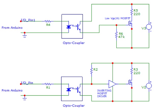
Put an opto-coupler ahead of the MOSFET. That way you only need to drive the LED side of the opto-coupler with the Arduino. You would then connect the switching side of the optocoupler to the MOSFET gate and the other side to the isolated 5 V supply. To get better drive and the correct logic you might also want to add an extra MOSFET driver or transistor between the opto-coupler and the gate. Last but not least, placing a high value resistor from the gate to source will help insure that the MOSFET stays off when it should be off.

Two typical examples using an opto-coupler:

enter image description here

\$\endgroup\$
5
  • \$\begingroup\$ Thank you for the answer, but I can't correctly make out the circuit. Could you provide a simple schematic? \$\endgroup\$
    – Carl
    Commented Oct 16, 2023 at 9:41
  • 3
    \$\begingroup\$ Floating GND is one of the reasons MIDI uses optocouplers \$\endgroup\$ Commented Oct 16, 2023 at 10:40
  • \$\begingroup\$ @Carl - Two example schematics added using opto-couplers. Note that I didn't give many specific values or P/N's as there are several variables to be decided on your part. \$\endgroup\$
    – Nedd
    Commented Oct 16, 2023 at 11:42
  • 3
    \$\begingroup\$ There are also MOSFET-output optocouplers that can be used as switches directly, no additional FET needed. \$\endgroup\$
    – Hearth
    Commented Oct 16, 2023 at 11:58
  • \$\begingroup\$ I'm not sure why everyone is still in love with optocouplers. This is a digital signal so why not use a digital isolator instead? More reliable. \$\endgroup\$
    – Lundin
    Commented Oct 17, 2023 at 14:13
4
\$\begingroup\$

You are attempting to obtain the impossible device that you asked about in this question

The problem is that the device you are describing is NOT a 3 terminal one - it is a 4 terminal one.
You have shown the "V_Arduino" voltage connecting to ground BUT are pretending that the ground connection does not constitute a terminal.
This is incorrect.

There are two terminals for the differential voltage.
There are two terminal for the control voltage.
You CANNOT have one connection "hang in the air" and pretend that it does not need to have a real world circuit involved.
The control circuit MUST have a reference point.

I explained in my two final substantial comments on your other question what you had to do and why.
I also noted that you needed to listen to what people tell you and understand it.
This is still required.

An opto coupler, suggested there and here, is one solution.
A discrete component solution is also possible BUT will need you to answer the questions asked on your other question.

\$\endgroup\$
3
\$\begingroup\$

If you are looking for a "nearly perfect" switch, then a relay should meet your requirements (it's an mechanical switch, excepted that it is moved by an electromagnet instead of my hand). So like a mechanical switch, you have "perfect" isolation (up to some breakdown voltage, often >1000V). You also have a real bidirectional switch (contrary to a MOSFET, that can't block reverse current).

The main drawbacks are :

  • bulkier than a mosfet for equal current capability
  • the electromagnet consumes current (usually in the 50mA-300mA range)
  • because of the "high" current and inductive nature of the electromagnet, you need to add a Mosfet and a free-wheeling diode to drive the relay from the arduino (NB : if you do quick prototyping or a hobby project, you can use relay modules for arduino that already include all this stuff, so you can connect it directly to an arduino GPIO)
  • it's more expensive than a mosfet

The other solution, as @Nedd suggested, is to use an optocoupler (or a digital isolator) and a NMOS

\$\endgroup\$
3
  • 1
    \$\begingroup\$ There's also the intermediate case, a MOSFET (or antiseries pair) with opto driver, no external supply required, just the LED. \$\endgroup\$ Commented Oct 16, 2023 at 10:03
  • \$\begingroup\$ There is also an issue with relays, in some cases, that their lifetime can be significantly shorter (fewer on-off cycles before failure) than a solid state device. This depends on the devices in question and is only relevant if the number of cycles will ever reach the relay lifetime. \$\endgroup\$ Commented Oct 17, 2023 at 17:42
  • \$\begingroup\$ For interest only: Reed relays can have coil currents under 5 mA - suitable for operation from an Arduino pin in selected cases. One in this r=table is rated at 3.75V at 5 mA. Price is not nice. I'd use a coupler of some sort. digikey.co.nz/short/58tj9bn3 \$\endgroup\$
    – Russell McMahon
    Commented Oct 18, 2023 at 3:42
0
\$\begingroup\$

Using a 2N7000 is a poor choice. You need a logic level FET. IRLB8721 is an example, but might be overkill if you switch small currents.

\$\endgroup\$
2
  • 8
    \$\begingroup\$ Any MOSFET is a poor choice without a common ground reference. \$\endgroup\$ Commented Oct 16, 2023 at 10:02
  • \$\begingroup\$ Good spotting there. \$\endgroup\$
    – MiNiMe
    Commented Oct 16, 2023 at 10:03

Your Answer

By clicking “Post Your Answer”, you agree to our terms of service and acknowledge you have read our privacy policy.

Not the answer you're looking for? Browse other questions tagged or ask your own question.