4
\$\begingroup\$

In most of the devices I have seen so far, the absolute maximum ratings of the pins of the IC are given with respect to voltage.

For example, the maximum voltage applicable on a pin would be something like, 0V to Vcc+0.5V.

My question, why is the maximum rating given in terms of voltage and not current?

Also, a follow-up question scenario.

Suppose, I have an IC whose Vcc is 5V and is unpowered.

I give 5V to a GPIO pin. In this case, the absolute maximum rating of the pin is exceeded because, the maximum voltage of Vcc+0.5V is violated for the particular pin. It is 5V instead of 0.5V now.

So, I assume the pin will damage. But what I thought is that, as long as I keep the current going into the pin very minimal I will not damage the IC pin. Because, since the GPIO pin will be either connected to Vcc or GND internally. If the pin is connected to Vcc internally, then the voltage on the Vcc would be 5V - 0.5V (ESD Clamping diode Vf). Hence, Vcc would be 4.5V. Maybe, I will put a series resistor on the pin such that the current flowing into the pin will be in the range of microamps and hence, this current will flow through the ESD diode and will not damage the device.

Is my thought process correct? What would be a better solution?

\$\endgroup\$
4
  • \$\begingroup\$ Provide link to datasheet that illustrates each of the questions you are asking. The maximum voltage to a pin is often less than a diode drop above Vcc or below ground for good reason. But there are usually other specs that relate to this (and protection diodes, lock-up, etc.) Details matter. So links will clarify your question that you may not be able to clarify, yourself. But yes, if Vcc=0 then there will be problems. But it's probably not spec'd well when Vcc=0, either. So who knows? Need datasheet. Even then, there may not be a good answer for Vcc=0. \$\endgroup\$ Commented Nov 16, 2023 at 13:31
  • \$\begingroup\$ I don't quite understand your question. What exactly is your rated nominal VCC? If VCC is 5V, your pin can support up to 5.5V if absolute max is VCC+0.5V. Exceeding Absolute maximum ratings usually leads to abnormal behaviour of components in the best, physical destruction in the worst case. \$\endgroup\$
    – S_G
    Commented Nov 16, 2023 at 13:33
  • 1
    \$\begingroup\$ And yes, keeping the current minimal helps. Protection diodes can often only handle 1 or 2 mA, at most. Aluminized tracks in the device will have their own limitations, too. (Metal migration, if nothing else.) You probably need to provide specific details about what you are thinking about doing. Not just asking very broad questions like this. \$\endgroup\$ Commented Nov 16, 2023 at 13:33
  • \$\begingroup\$ some inputs float when VCC is zero, ex open collector. Most MCU GPIOs are totem poles, and there can be a route back to vcc from an IO. I've see the built-in LED on ESPs glow when powered off but backfed from a GPIO sensor input. It didn't seem to damage it, but you probably don't want to design something where that happens all the time. \$\endgroup\$
    – dandavis
    Commented Nov 17, 2023 at 4:08

3 Answers 3

4
\$\begingroup\$

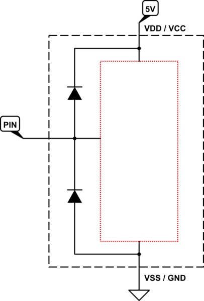
For example, the maximum voltage applicable on a pin would be something like, 0V to Vcc+0.5V.

This is generally due to the presence of internal clamping and/or ESD diodes:

schematic

simulate this circuit – Schematic created using CircuitLab

My question, why is the maximum rating given in terms of voltage and not current?

Current ratings are given for some ICs and applications. For example, for MCU context, GPIO sink and source current ratings which are part of absolute ratings, are always given.

So, I assume the pin will damage.

Not always. We can't say neither "Yes" nor "No" without any context. But we can make some assumptions:

  • VDD/VCC pin is floating whilst GND is connected and you applied 5V to the GPIO. The IC may try to draw current to power itself up and this may or may not kill the clamping diode if its current rating (which is generally a few/one-digit milliamps) is exceeded.

  • VDD/VCC = 5V and you applied 6V to the GPIO. In this case the clamping diode will clamp the pin voltage to somewhere around 5.5 VDC but it may or may not die. Because, during clamping, the current will be limited by the clamping diode's internal resistance and the output impedance of the thing that applies 6V to the pin. If this current is kept below some limit then diode may survive.

  • VDD/VCC is shorted to GND and GND is connected, and you applied 5V to the GPIO. In this case the pin voltage will be clamped to diode's forward voltage which is around 0.3 ~ 0.5V. And the current will be limited by the dynamic resistance and the output impedance of where that 5V is coming from.

The above scenarios don't tell you that it always makes sense to limit the current at/below some level. There are cases where the input impedance brings a limit: Assume the internal clamping diode's max current rating is 2 mA (not given, just an assumption) and you limited the current at 0.5 mA with an effective output resistance of ~10k. If the pin has an input impedance of 20k then during the normal operation the voltage seen by the pin will be 2/3 of nominal which may or may not cause some problems such as false readings.

So it depends on the application, context and limits.

\$\endgroup\$
6
\$\begingroup\$

Your assumptions are mostly correct. Many chips have ESD protection diodes from the pins to VCC, and it is the power dissipation of the current flowing through them that would damage them. The limit of VCC + 0.5 V simply ensures that no noticeable current actually flows.

There are datasheets that tell you about the current that would still be safe, e.g., that of the SN74AC00:

SN74AC00 absolute maximum ratings

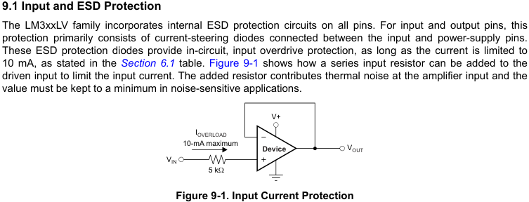
And some op-amp datasheets explicitly say how a resistor can be used to implement such a current limit, e.g., LM358LV:

LM358 input and ESD protection

If the datasheet does not tell you about a current limit, then you could assume that some very low value like 50 µA would be safe. But that would be just an assumption.


And there are chips that do not have clamping diodes to VCC; usually to allow input voltages somewhat higher than VCC, e.g., SN74AHC00 below (note that clamping happens only for negative voltages). For those, a current limit would not help against overvoltage above the limit, because the gate isolation would break down and get damaged if any amount of current starts to flow.

SN74AHC00 absolute maximum ratings

\$\endgroup\$
1
\$\begingroup\$

Bad idea.

The current flow into the pin will raise VCC above zero, turning the MCU on at some point. A series resistor changes only the time that this procress would take.

Crowbar type circuits are very rare in MCU applications.

Draw a complete schematic. This would allow you -or us- to look for a good solution to your specific problem.

Note that there are MCUs with GPIO pins that don't have a VCC dependency in the allowed voltage range. But often these also cannot output "high" on these pins as the high side switch transistor is omitted.

\$\endgroup\$

Your Answer

By clicking “Post Your Answer”, you agree to our terms of service and acknowledge you have read our privacy policy.