0
\$\begingroup\$

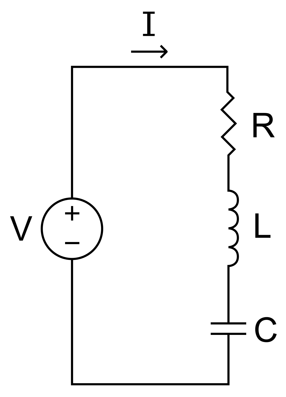
The original transfer function is I(s) over V(s) for a basic circuit that contains a resistor, inductor and a capacitor with a voltage source (Basic RLC circuit) where R is the resistance of the resistor, C is the capacitance of the capacitor and L being the inductance of the inductor.

Why does Vc(s) = I(s) / s when trying to convert the transfer function to be Vc(s) over V(s)?

My college uses the Laplace table without any complex integration needed for now so answers using the Laplace table would be better and be greatly appreciated

enter image description here

enter image description here

\$\endgroup\$
3
  • \$\begingroup\$ You haven't shown the schematic and where the output is taken from. \$\endgroup\$
    – Andy aka
    Commented Nov 20, 2023 at 12:53
  • \$\begingroup\$ Assuming zero initial conditions, Vc(s)=Ic(s)/(sC), VL(s)=sLI(s), Vr(s)=RIr(s). \$\endgroup\$ Commented Nov 20, 2023 at 13:04
  • \$\begingroup\$ Y(s)=Cs/(CLs^2+CRs+1)=s/[L(s^2+Rs/L+1/(LC)] \$\endgroup\$ Commented Nov 20, 2023 at 13:17

2 Answers 2

1
\$\begingroup\$

Well, the current in the circuit is given by:

$$\text{I}\left(\text{s}\right)=\frac{\displaystyle\text{V}_\text{source}\left(\text{s}\right)}{\displaystyle\text{R}+\text{sL}+\frac{\displaystyle1}{\displaystyle\text{sC}}}\tag1$$

So, the voltage across the capacitor is given by:

$$\text{V}_\text{C}\left(\text{s}\right)=\frac{\displaystyle1}{\displaystyle\text{sC}}\cdot\text{I}\left(\text{s}\right)=\frac{\displaystyle1}{\displaystyle\text{sC}}\cdot\frac{\displaystyle\text{V}_\text{source}\left(\text{s}\right)}{\displaystyle\text{R}+\text{sL}+\frac{\displaystyle1}{\displaystyle\text{sC}}}\tag2$$

So, your (or the books) solution is right when \$\displaystyle\text{C}=1\space\text{F}\$.


Just for completeness, the time-domain solution of the voltage across the capacitor is given by:

$$\text{v}_\text{C}\left(t\right)=\frac{\displaystyle1}{\displaystyle\text{C}}\int\limits_0^t\text{v}_\text{source}\left(\tau\right)\cdot\left(\int\limits_0^{t-\tau}\mathscr{L}_\text{s}^{-1}\left[\frac{\displaystyle1}{\displaystyle\text{R}+\text{sL}+\frac{\displaystyle1}{\displaystyle\text{sC}}}\right]_{\left(\sigma\right)}\space\text{d}\sigma\right)\space\text{d}\tau\tag3$$

\$\endgroup\$
1
\$\begingroup\$

Why is the voltage across a capacitor in the Laplace domain equals I(s) / s?

It isn't.

\$1/s\$ means integration, so \$I(s)/s\$ means integrating \$i(t)\$ over time i.e. \$\int i\ dt\$. This is because \$s=j\omega=d/dt\$ for non-decaying, constant-frequency sinusoidal inputs.

Integrating the current waveform (sinusoid) over time doesn't give you the voltage (sinusoid) unless there's a unity capacitance that links voltage and current. But no component values are given so we can't make the \$V(s)=I(s)/s\$ conversion.

answers using the Laplace table would be better and be greatly appreciated

Laplace table is a table of some well-known/common functions and their Laplace transforms such as \$\mathcal{L}\{f(t)=1\}=1/s\$ or \$\mathcal{L}\{f(t)=e^{at}\}=1/(s-a)\$. For your case there's no such (or similar) conversion/transform/replacement because everything is written in s-domain already so I don't think the Laplace table could be of use here.

\$\endgroup\$

Your Answer

By clicking “Post Your Answer”, you agree to our terms of service and acknowledge you have read our privacy policy.

Not the answer you're looking for? Browse other questions tagged or ask your own question.