5
\$\begingroup\$

Apologies if it’s obvious but I always hear that differential pairs have a negative and positive waveform (one on each line) that’s opposite. Now I get that you could choose whatever value or point “Ground” is and just have the pulses swing around that point. And its that reason why the grounds between two diff pairs does not matter since its just the difference that matters . But I struggle to see how the negative line could be at a voltage negative with respect the ground reference used to make that actual signal. Say for example on USB, is the negative line of the pair actually below the GND line of the USB? Or is it a case of the negative of the diff pair could be 0-2V and the positive line 2-4V (with respect to the actual USB ground)?

Hope my question makes sense

\$\endgroup\$

5 Answers 5

2
\$\begingroup\$

In the story below, I have introduced the idea of differential signaling step by step, in the form of an imaginary story. I have illustrated it by a series of CircuitLab experiments (I think this will be more interesting to the OP than only lengthy verbal explanations). To make my explanations more impactful and "low-level", I have not used the more sophisticated Sweep DC Simulation and Time-Domain Simulation but only the simple Live DC simulation. Also, I have visualized the DC voltages by ordinary DC voltmeters. This is a concept (well-known for a long time) and therefore we do not need to draw detailed electronic circuits; a few voltage sources and voltmeters are enough to show the idea.

1.Single-ended configuration

The simplest way to connect a voltage source to the input of an amplifier is by a single wire; the other is the ground. The problem with this connection is that if unwanted disturbances (voltages) are induced in the signal (left) wire, they are added to the input voltage in series, according to KVL. For example, in the schematic below, 100 mV induced voltage (noise) is added to 1 V input voltage; as a result, 1.1 V are applied to the voltmeter. Note the unusual way of drawing - the input is at the bottom rather than the conventional left, and the output is at the top rather than the right.
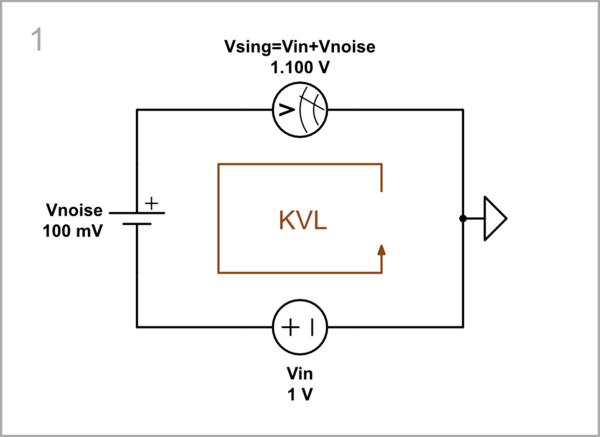
schematic

simulate this circuit – Schematic created using CircuitLab

2.Differential configuration

2.1.Conceptual circuit

The solution is to make the two wires equal; then the two induced voltages VnoiseL and VnoiseR will be oppositely connected in the loop, and will cancel each other out. To do this, we can split the input voltage source Vin into two sources - Vin1 and Vin2, and ground the middle point. The ("floating") amplifier input will receive a differential voltage Vd = VnoiseL + Vin1 - Vin2 - VnoiseR = Vin1 - Vin2. We can name this clever trick passive compensation and use, when needed, in the future.

So the general idea is to transmit over two wires the difference between two input voltages as an input signal.
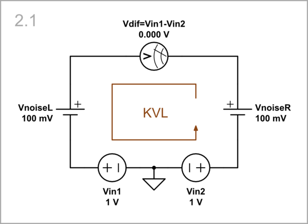
schematic

simulate this circuit

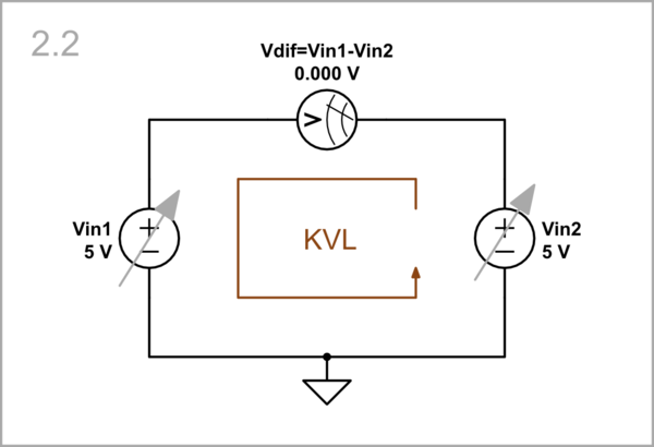
2.2.Common-mode

Vin1 = 5 V, Vin2 = 5 V: From the schematic above, we see that if the two input voltages are equivalent (like the noise voltages), the result is a zero differential voltage (it remains so even if we start changing them simultaneously in the same way and stop in the middle - 5 V). So we can suppress uniform changes of input voltages (so-called "common mode") in the same way as we suppressed noise voltages.
schematic

simulate this circuit

To have an input signal, we need to create a difference between the two input voltages. We can do it in several ways as follows:

2.3.Single-ended differential input

First, we can change only one of the input voltages and keep the other constant.

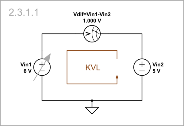
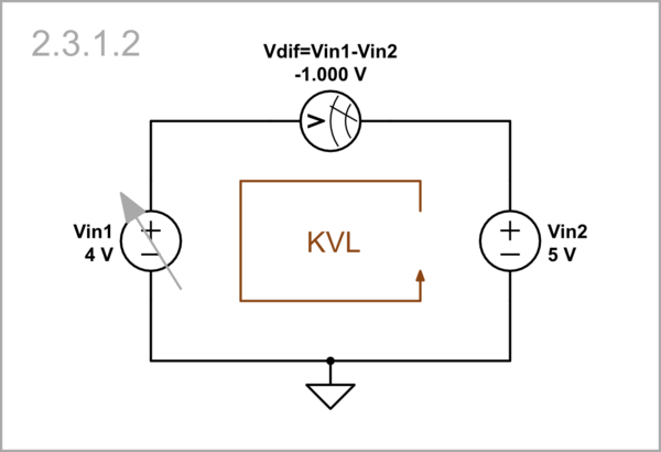
2.3.1.Left input: If we start with Vin1...

Vin1 = 6 V, Vin2 = 5 V: ... we can first increase it with 1 V above 5 V...
schematic

simulate this circuit

Vin1 = 4 V, Vin2 = 5 V: ... then decrease it with 1 V below 5 V.
schematic

simulate this circuit

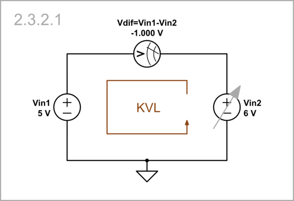
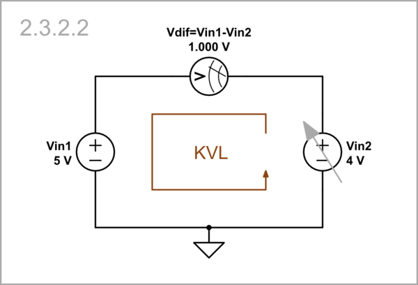
2.3.2.Right input: Then we continue with Vin2...

Vin1 = 5 V, Vin2 = 6 V: ... first increasing it with 1 V above 5 V...
schematic

simulate this circuit

Vin1 = 5 V, Vin2 = 4 V: ... and then decreasing it with 1 V below 5 V.
schematic

simulate this circuit

2.4.Fully differential input

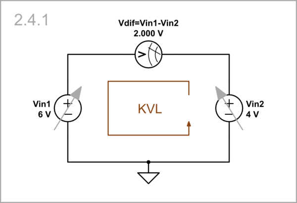
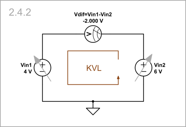
We can make this differential configuration completely symmetrical if we simultaneously change both input voltages in different directions...

Vin1 = 6 V, Vin2 = 4 V: ... first Vin1 with 1 V up and Vin2 with 1 V down...
schematic

simulate this circuit

Vin1 = 4 V, Vin2 = 6 V: ... then Vin1 with 1 V down and Vin2 with 1 V up.
schematic

simulate this circuit

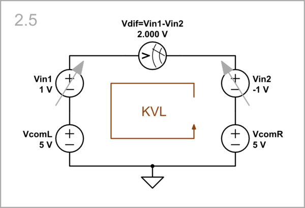
2.5.Separate common-mode input sources

Vin1 = 1 V, Vin2 = -1 V: We can imagine that the common-mode voltage is produced by two identical 5 V voltage sources VcomL and VcomR respectively connected in series to the input sources (e.g., Vin1 = 1 V and Vin2 = -1 V). Note that both total single-ended input voltages "VcomL + Vin1" and "VcomR + Vin2" are positive.
schematic

simulate this circuit

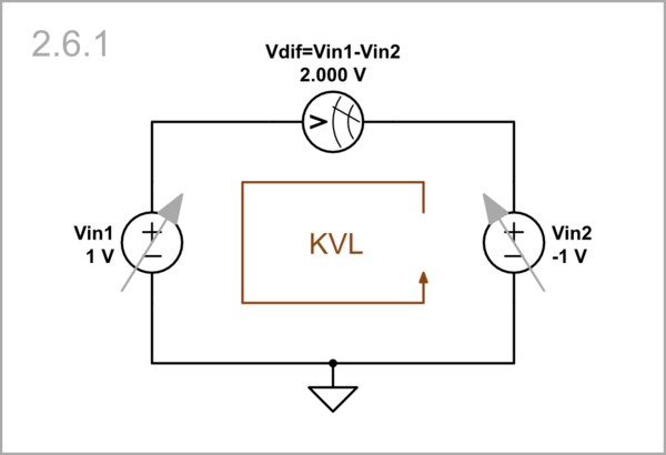
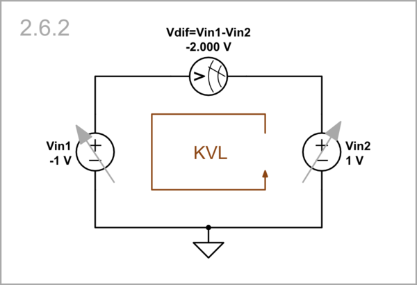
2.6.Pure differential mode

If the common-mode voltage is zero, there is a pure differential mode. Now one of the input voltages drops below zero -

Vin1 = 1 V, Vin2 = -1 V: ... Vin2...
schematic

simulate this circuit

Vin1 = -1 V, Vin2 = 1 V: ... or Vin1.
schematic

simulate this circuit

\$\endgroup\$
7
\$\begingroup\$

The differential voltage - carrying the information - tells you nothing about the voltage the individual lines are swinging around.

In fact it's not very common for any line to swing below the potential someone would generally call "GND".

If the positive line is at 5V with respect to GND and the negative line is at GND, the differential signal is +5V. If the negative line is at 5V with respect to GND and the positive line is at GND, the differential signal is -5V.

Although the differential voltage can have a minus sign, at no point in time any individual line is actually below GND.

What voltage with respect to GND the individual lines are swinging around depends on the differential signaling standard. LVDS for example swings around approx. 1.2V with respect to GND.

\$\endgroup\$
5
\$\begingroup\$

enter image description here

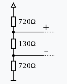
Figure 1. RS485 biasing network. Image by Stündle, Creative Commons. Note that both lines are biased positive and with the resistor values shown the + and - lines will be roughly 55% and 45% of supply voltage in the idle state.

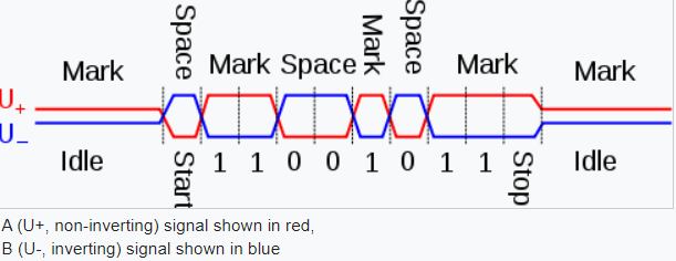
From the same source:

enter image description here

Figure 2. Switching of the RS485 signal.

USB will be similar.

Or is it a case of the negative of the diff pair could be 0 - 2 V and the positive line 2 - 4 V (with respect to the actual USB ground)?

Generally not. The two inputs will be fed into a comparator and what you really want is polarity inversion at the inputs for clear logic levels. The signals are compared with each other rather than to an absolute reference.

\$\endgroup\$
4
\$\begingroup\$

Label the wires of a differential pair as \$a\$ and \$b\$. The voltages \$V_a\$ and \$V_b\$, relative to an arbitrary voltage (\$V_{ref}\$), swing above and below the average of the two voltages,$$V_{ave}=\frac{(V_a+V_b)}{2}$$

Therefore it can be said that the voltages \$V_a\$ and \$V_b\$ do go negative relative to their average voltage, but not necessarily ground (0V).

5V USB signals go negative relative to 2.5V not GND.

\$\endgroup\$
2
  • 3
    \$\begingroup\$ Small correction, low to Full Speed USB is 3.3V, basically HCMOS logic level/strength. In High Speed mode, it's 0/400mV relative to GND. Also note that USB isn't fully differential, as the SE0 symbol utilizes the common mode. \$\endgroup\$ Commented Nov 26, 2023 at 2:24
  • 1
    \$\begingroup\$ @TimWilliams Just to round out the comment: low to high speed USB are not fully differential, but superspeed USB is. \$\endgroup\$
    – Hearth
    Commented Nov 27, 2023 at 7:17
1
\$\begingroup\$

Edited: The answer in this case is no.

One further example is so called phantom power used in powering (professional) microphones. The microphone preamp outputs +48 V on both "hot" and "cold" signals as compared to the "ground" *). The microphone draws power used for the internal circuits. The signal is then output differentially on "hot" and "cold" - neither of them will ever go below zero.

*) Detail: the +48V is connected using two resistors of 6.8 kOhm. (Note: the description is for P48 according to IEC 61938, there are variations).

\$\endgroup\$
2
  • \$\begingroup\$ Please note that while the signal on "hot" and "cold" wires are differential between them, their DC bias is rather irrelevant, sure with phantom power they are at +48V but without it their DC bias is 0V. Also note that while "hot" and "cold" wires are both differential and balanced, it does not mean both wires will have an audio signal. A mic could output the signal on "hot" or "cold" wire alone, since it's the differential voltage between "hot" and "cold" that matters. \$\endgroup\$
    – Justme
    Commented Nov 26, 2023 at 13:38
  • \$\begingroup\$ @justme You are correct. There are a lot of special cases. \$\endgroup\$
    – ghellquist
    Commented Nov 26, 2023 at 21:22

Your Answer

By clicking “Post Your Answer”, you agree to our terms of service and acknowledge you have read our privacy policy.

Not the answer you're looking for? Browse other questions tagged or ask your own question.