1
\$\begingroup\$

I'm interested in building a solid state relay module at home using a triac.

I know the safety risks associated with this project. I'm also aware of the cheap SSR modules capable of the same things. Regardless, I'm determined to learn how to do this myself.

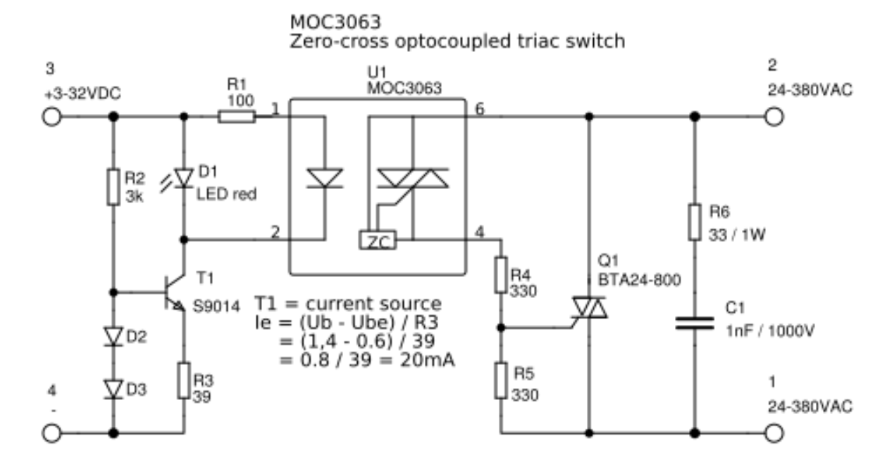
I'm using this schematic of an existing SSR as a guide. I understand the input side of the optocoupler.

enter image description here

I'm really struggling to find resources that explain how to compute the following about the triac:

  1. The gate current. It seems like I'll need the voltage from the gate to MT1/MT2. Is this near-constant like V_be for an NPN BJT?

  2. The voltage between MT1 and MT2 given a load.

Any guidance would be greatly appreciated. Information online seems sparse, so I'm not sure if I'm asking the right questions.

\$\endgroup\$
1

2 Answers 2

1
\$\begingroup\$
  1. Yes, the gate voltage with current flowing is typically around 1 volt. Plus or minus.

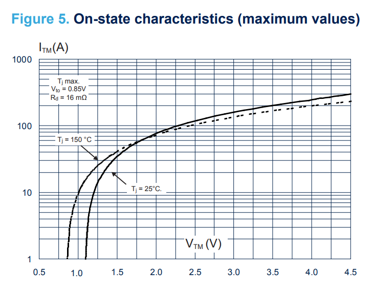
  2. The voltage between MT1 and MT2 when 'on' is important to power dissipation so you'll usually find it well specified in the datasheet. Again, it's typically around a volt or so with the triac conducting normal load current (positive or negative).

enter image description here

Triacs are very old technology and have not changed much for better or worse in 50+ years, so the basic information about them tends to be more available in old documents such as the GE SCR manual.

In the case of your SSR, the gate current to trigger the triac comes from the mains through the load. If you think of R4 as a short and R5 open, it will not affect the basic function. They're there to deal with secondary effects such as leakage, dv/dt and triggering of the opto-triac from transients.

\$\endgroup\$
3
  • \$\begingroup\$ Thanks for the answer! Is there a datasheet parameter that specifies the gate voltage when current is flowing, or should I just assume it to be around 1V for all triacs? \$\endgroup\$
    – user120632
    Commented Dec 4, 2023 at 17:50
  • 1
    \$\begingroup\$ Vgt specifies the maximum gate voltage when a trigger current is applied to the gate. In the datasheet I linked it's 1.3V (max) in all 3 specified quadrants. When the triac is conducting, a bit of voltage comes out of the gate. This is not well specified, but it will be similar (and of course it will be less than, and the same polarity as, the 'A2' voltage with respect to 'A1') and there will be some internal series resistance (again, not well specified). \$\endgroup\$ Commented Dec 4, 2023 at 21:10
  • \$\begingroup\$ Thank you for all the help! \$\endgroup\$
    – user120632
    Commented Dec 5, 2023 at 20:26
2
\$\begingroup\$

First realize that this circuit cannot create true zero-cross switching since it relies on the voltage at MT2 to fire the gate. The goal is to get it reasonably close to zero.

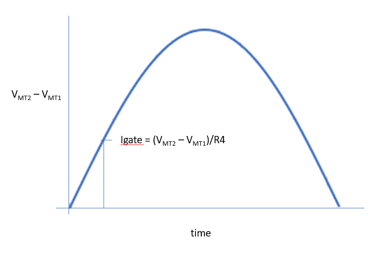
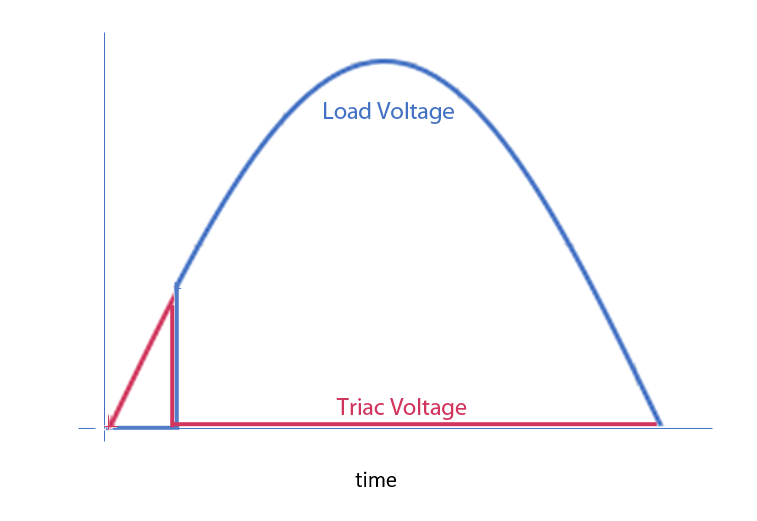
The value of R4 is a compromise. You want a small value so the gate triggers near zero. This circuit always uses triac quadrants I or III, so the maximum required gate current is 50 mA. It will typically be much less. The maximum voltage at the trigger point with an R4 of 330 ohms will be about 0.05A * 330 = 16 Volts.

If R4 is really small, you risk damaging the triac if the opto doesn't properly zero-cross.

You also need to be sure that the peak and average power dissipated by R4 is within the capability of the resistor.

An R4 value of 330 ohms is reasonable for the line voltage specified. If your voltage is always lower than this, you could reduce the value of R4 some.

To calculate the average power in R4, you need to integrate the little red piece of sine wave in the second picture.

R5 isn't critical, but you want something there so parasitics don't trigger the triac.

enter image description here

enter image description here

The left side of your circuit is a crude current limiter. If you don't need to control the circuit from a wide range of voltages, you don't need that complexity.

\$\endgroup\$

Your Answer

By clicking “Post Your Answer”, you agree to our terms of service and acknowledge you have read our privacy policy.

Not the answer you're looking for? Browse other questions tagged or ask your own question.