1
\$\begingroup\$

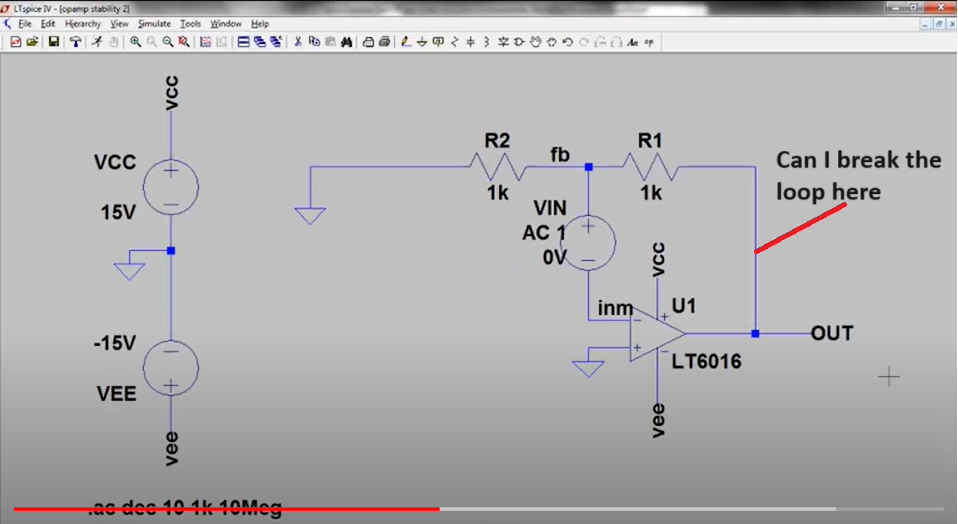
I am studying the stability of op-amp circuits using LTspice with the help of this video. I can see many threads on Stack Exchange like this one, but the explanation is not clear to me.

I have a couple of questions regarding this.

  1. For checking the gain peaking, the loop is not broken. Why is the phase margin not available from that gain peaking plot?

  2. For finding the PM, the loop is broken and a source is placed with DC = 0 and AC = 1. Why?

  3. What will happen if I provide some other value like DC = 5 V instead of DC = 0?

  4. Can I break the loop anywhere?

  5. Is there any method to test the stability without breaking the loop?

  6. In both cases (gain peaking and PM) the input source is made zero. Why?

enter image description here

\$\endgroup\$

2 Answers 2

4
\$\begingroup\$

Answers to

1.) Phase margin is defined for the loop gain only. Of course, stability properties have an influence on closed-loop peaking. However, we cannot quantify the margin in this case.

Exception: For a second-order circuit we can find a relation between (positive) phase margin and the amount of peaking as well as overshooot (step response).

2.) For measuring/simulating the loop gain we must open the loop and inject an AC test signal. Condition: Same DC operating point and same load conditions at the opening as under closed-loop conditions. Therefore, no extra test DC voltage allowed. Comment: The DC operating ponz remains unchanged because the test signal source is connected BETWEEN both nodes of the opening (and NOT between loop input and ground).

3.) See 2)

4.) In principle - yes. However, under the mentioned constraints (see 2) it makes sense to find a node for breaking the loop where a low output resistance meets a high input resistance (Opamp case: opamp output or high-impedance input). Only in this case, we must not use an "artificial" additional load to restore the closed-loop load conditions.

5.) When you want to qualify the stability properties: No, the test must be performed for the loop open (loop gain). If you need the information "stable or not stable" it is sufficient to analyze the closed-loop operation.

6.) For finding the loop gain we must measure the signal strength at the output of the loop (at the opening) as a function of the test signal only. Therefore, no other input signal allowed.

\$\endgroup\$
0
\$\begingroup\$

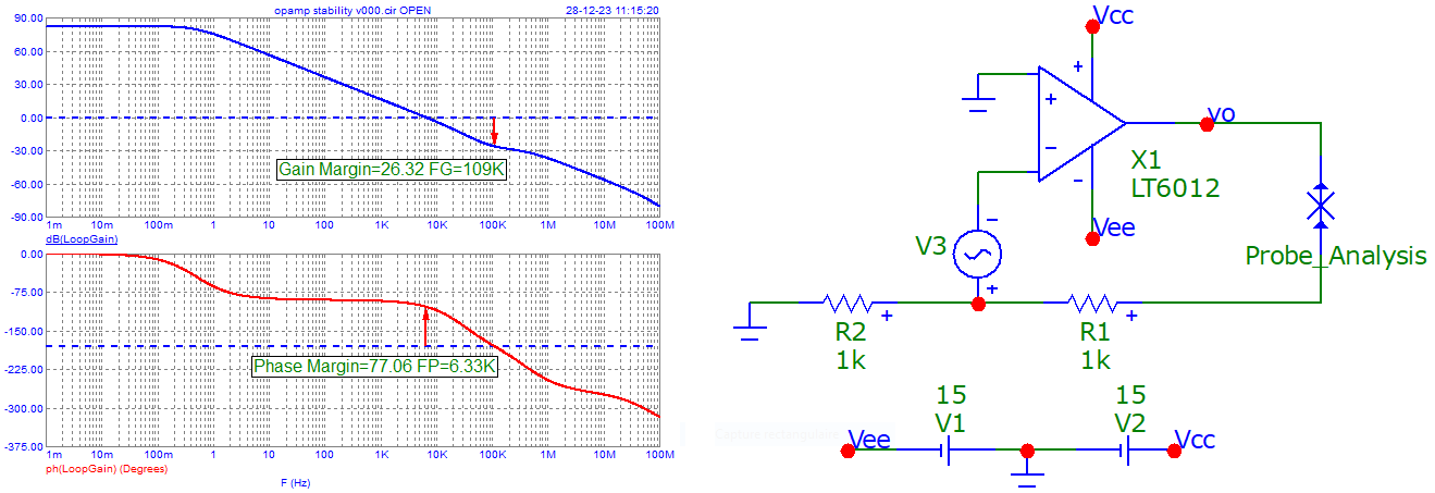
For completeness, I add a simulation made with microcap v12.

This simulator do the analysis without "cutting" anything, just insert the "symbol".

enter image description here

\$\endgroup\$
3
  • 1
    \$\begingroup\$ I cannot follow your simulation. Only 80 db max. loop gain? Should be 3dB below the opamps open-loop gain Aol (which is much larger!). How did you simulate the loop gain? What is the meaning of the "X" at the most right side of your figure? \$\endgroup\$
    – LvW
    Commented Dec 28, 2023 at 10:52
  • 1
    \$\begingroup\$ It is the 'tool' for tracing the plots at the left. Nb: the opamp is not the same than yours. I did not had it in my 'library'. \$\endgroup\$
    – Antonio51
    Commented Dec 28, 2023 at 15:23
  • \$\begingroup\$ Ther must be an error. The loop gain is just the ratio of the two (simulated) voltages at both sides of the test voltage V3. This is in accordance with the definition of loop gain. As an alternative, you can insert V3 at the location where the "X" is shwon. \$\endgroup\$
    – LvW
    Commented Dec 28, 2023 at 19:47

Your Answer

By clicking “Post Your Answer”, you agree to our terms of service and acknowledge you have read our privacy policy.

Not the answer you're looking for? Browse other questions tagged or ask your own question.