Including a resistance in the emitter path is called "emitter degeneration". Consider these scenarios, with different resistances at the emitter:
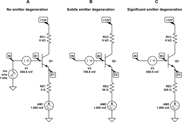
simulate this circuit – Schematic created using CircuitLab
Note that \$R_{E1} = 0\Omega\$, effectively tying node E1 to ground, and fixing its potential at 0V.
Sources V1, V2 and V3 are chosen to bias the base-emitter junctions to pass exactly 1mA in each case. Otherwise they can be disregarded, as all we are really interested in is how emitter current \$I_E\$ (and consequently collector current) changes as a result of changes in potential \$V_{B}\$, as opposed to any absolute potential there. That is, we want to see how transconductance \$\frac{\Delta I_E}{\Delta V_B}\$ is affected by the presence of a resistance \$R_E\$ in the emitter path.
Base potential may rise and fall, but the amount by which emitter potential \$V_E\$ rises and falls may or may not be the same.
On the left, where the emitter is connected directly to ground, of course we have:
$$ V_{BE} = V_B - V_E = V_B - 0 = V_B $$
The Ebers-Moll equation is at work here:
$$ I_C = I_S \left( e^{ \frac{V_{BE}}{V_T} } - 1 \right) $$
With emitter potential fixed at 0V, so that \$V_{BE}=V_B\$, this equation needs no "tweaking". However, the second and third circuits, B and C, do not behave the same way.
Circuits B and C permit the emitter to rise in potential, above 0V. The amount by which they rise is determined by Ohm's law. For any given emitter current \$I_E\$, \$V_E\$ will be:
$$ V_E = I_ER_E $$
Now we need a new expression for \$V_{BE}\$ as a function of emitter current \$I_E\$:
$$
\begin{aligned}
V_{BE} &= V_B - V_E \\ \\
&= V_B - I_ER_E \\ \\
\end{aligned}
$$
As you pointed out, \$I_C \approx I_E\$, and we can plug in this expression for \$V_{BE}\$ into the Ebers-Moll equation:
$$ I_E \approx I_S \left( e^{ \frac{V_B-I_ER_E}{V_T} } - 1 \right) $$
Put another way, the presence of \$R_E\$ is reducing the change in emitter current \$I_E\$ that would result from any given change in base potential \$V_B\$.
A simulation will demonstrate this nicely. In my schematic, Source \$V_{IN}\$ is a 1mV amplitude sinusoid. Here's a plot of how emitter currents vary as \$V_B\$ is rising and falling by 1mV:
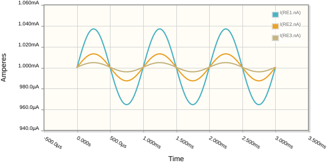
The blue trace is \$I_{E1}\$, where there is no emitter resistance. It clearly has greater amplitude than the others, telling us that transconductance decreases with increasing \$R_E\$.
I suspect that you have the right idea, but you failed to account for the biasing of the transistor, which has been carefully engineered in my examples to recreate the exact same quiescent emitter current in each case. In other words, there is indeed a decrease in collector and emitter current due to the presence of \$R_E\$, all other things being equal.
Strictly speaking, there is a decrease in effective transconductance, but that's relating change in collector/emitter current to change in base potential, and is highly dependent on absolute quiescent values everywhere. You must be operating in the same portion of the \$V_{BE}\$ vs. \$I_C\$ curve (according to the Ebers-Moll model), in order to make valid quantitative claims regarding \$V_B\$ vs. \$I_C\$, otherwise you have two changing independent variables, instead of just one, \$V_B\$.
From an intuitive perspective, since emitter degeneration permits \$V_E\$ to vary, any change in \$V_B\$ is necessarily going to result in a smaller variation in \$V_{BE}\$ than the scenario with no emitter resistance at all. Of course, effective transconductance will fall. My modification of the \$V_{BE}\$ term in the Ebers-Moll equation more formally reflects that.
In case this isn't yet clear enough, I'll say it with even more different words: The Ebers-Moll equation is always true, with or without emitter degeneration; a certain change in \$V_{BE}\$ will always result in the same change in \$I_C\$ (assuming you are operating in the same region of the \$V_{BE}\$ vs. \$I_C\$ curve). In the context of your question, though, it is \$V_B\$ that you are controlling, not \$V_{BE}\$. The resulting change in \$V_{BE}\$ will depend on \$R_E\$, and is therefore different in each case.

