2
\$\begingroup\$

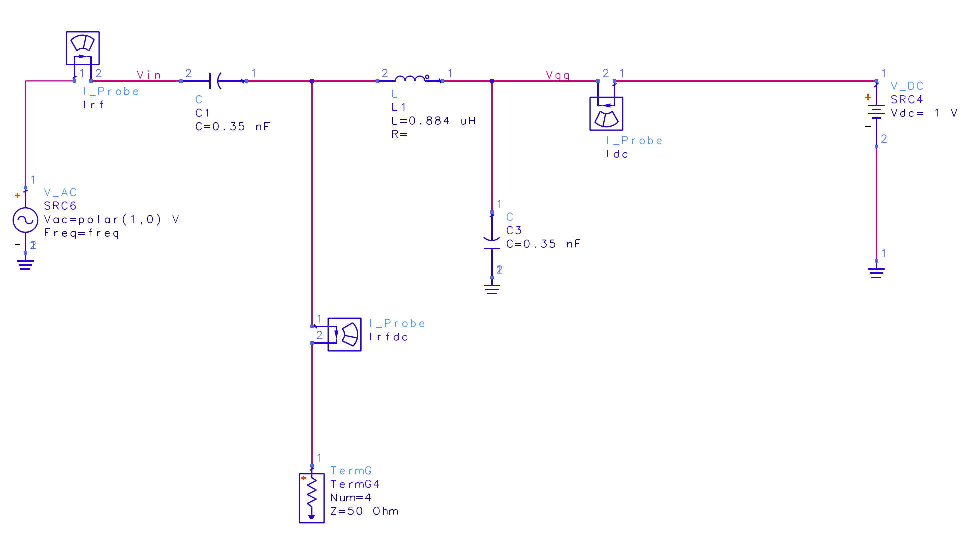
I am designing a bias tee here and wondered whether it actually works or not? Hence I conducted an AC analysis instead of S-parameters (after verifying that s parameters are okay). The bias tee has been designed for 900 MHz assuming 50 ohm impedances. So the circuit is as below:

enter image description here

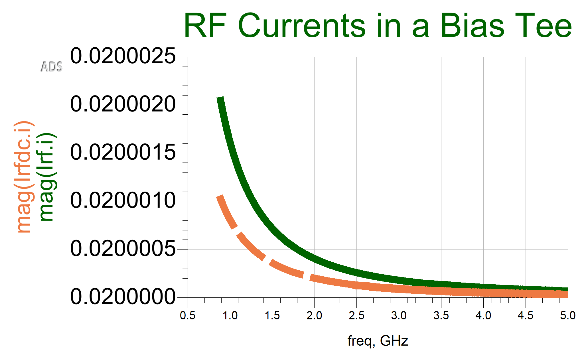
And the resulting currents are as below:

enter image description here

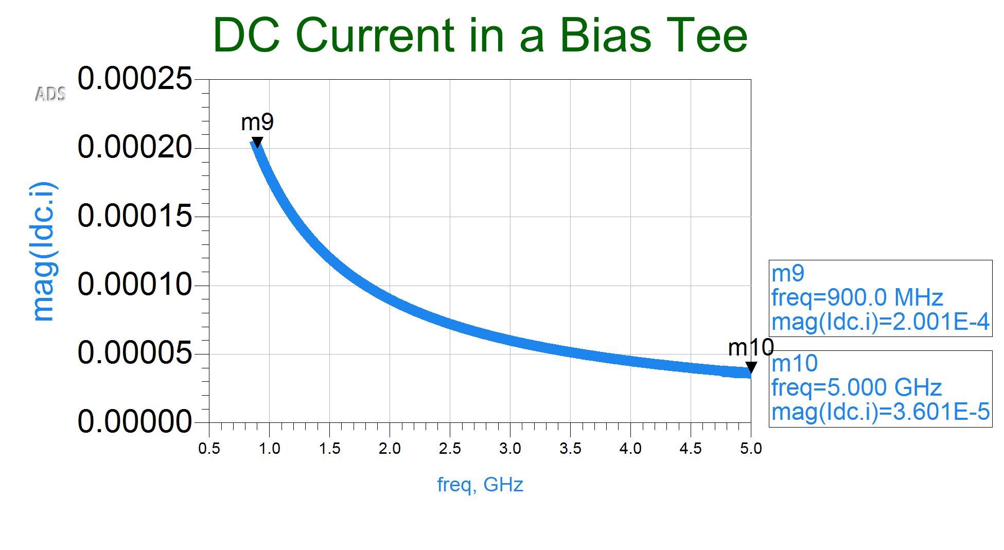
enter image description here

Now, my questions are:

  1. Why DC current is frequency dependent, it should have been a constant of about \$i=\frac{1 V}{50 \ \Omega}=0.02\ \mathrm A \$?
  2. Why the output (RFDC) current is smaller than the RF (input) current ? It should have been the addition of both currents, just shifted up by 0.2 A?
\$\endgroup\$

1 Answer 1

3
\$\begingroup\$

Why DC current is frequency dependent,

Because at low frequecies the inductor (L1) doesn't do a good job of blocking signals from the AC source

it should have been a constant of about \$i=\frac{1 V}{50 \ \Omega}=0.02\ \mathrm A \$?

The DC source (SRC4) doesn't have any effect on the AC simulation. AC simulations only calculate the response to the AC sources in the model.

Why the output (RFDC) current is smaller than the RF (input) current ?

Some of the current is going through the DC arm, because the inductor is an imperfect blocker at the frequencies being simulated.

\$\endgroup\$

Your Answer

By clicking “Post Your Answer”, you agree to our terms of service and acknowledge you have read our privacy policy.

Not the answer you're looking for? Browse other questions tagged or ask your own question.