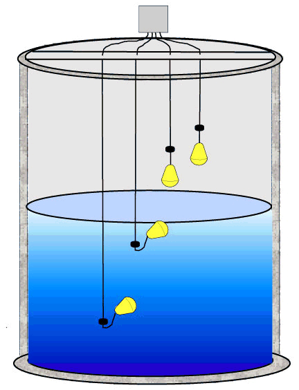
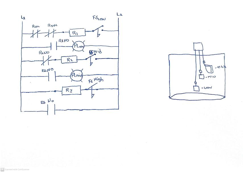
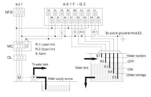
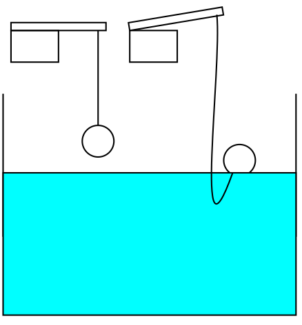
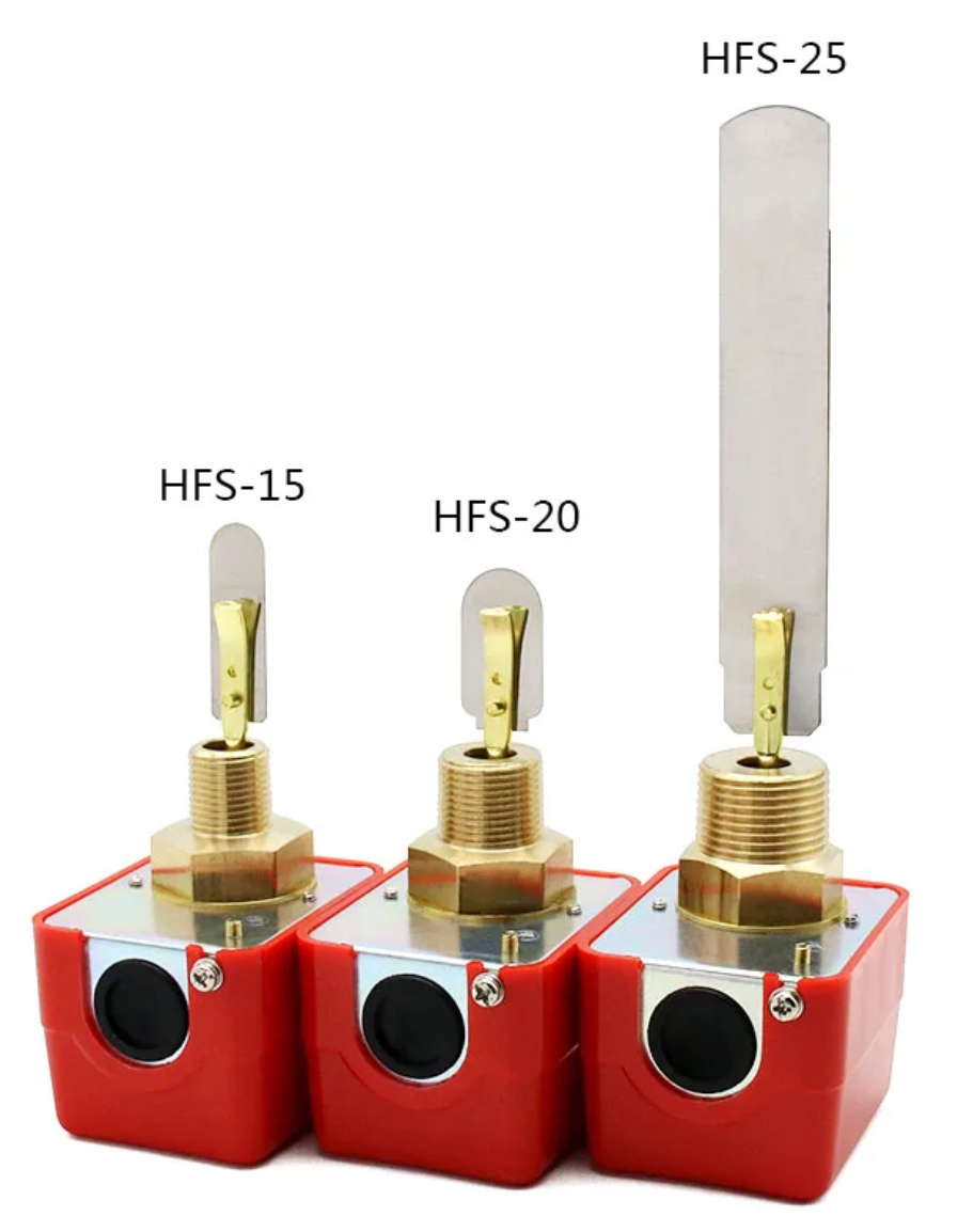
The lower limit float switch (E4) should be active low and high limit float switch (E1) should be active high.
What does it mean?
It means that when E4 switches off (assuming it switches off when it's above water level), it should turn on the low level indicator light and/or give a signal to stop the pump.
On the contrary, E1 should to turn on the high level indicator light and/or give a signal to start the pump when it switches on.
The main advantage of electronic is that we can build smart systems without sending 220V into the whole circuit through bulky and expensive components and therefore we avoid most of the hazardous situations.
It's perfectly possible, and even easier, to use low voltage and limited current in a pump control system. But for some reasons, with pumps, 75 years old technologies are still widely used as if time had stopped in the 50's.
Instead of sending 220V to the float switches, you can build a circuit based on 12VDC using the same float switches (albeit with some precautions) or, better, with devices designed for 12V (or similarly low voltage). Then all the risks are definitely away.
220V should only be at the relay actuating the pump and at the pump itself.
(Note that 12VDC and 24VDC pumps also exist, but their output is very slow.)
Everything else could and should be on safe, very low voltage.
Turning on or off one of the two light when E4 is open or when E1 is closed, if it's just to be aware of the level of the water, is relatively easy. However, these signals are not enough to turn on and off the pump because the signal from E1 is not permanent. So the E1 signal should trigger the permanent powering of the pump and the E4 signal should trigger the permanent turning off of the pump.
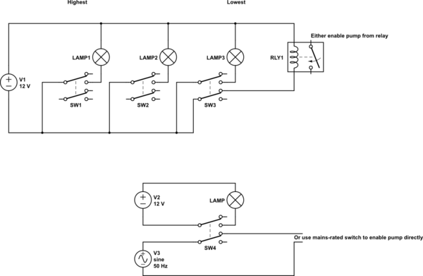
Here is a simplified schematic with only two indicator LED's telling you when the water ir high enough to turn on the pump and when it's low enough to turn it off.
When E1 is open, LED1 is off because it doesn't receive current. LED1 turns on when E1 is closed. It's active high.
When E4 is closed, LED4 is off because all the current supposed to go to the LED is going to the negative pole of the power supply (GND or V-). This current is very small because it's limited by the resistor. LED4 turns on when E4 is open and the current goes to the LED instead of GND. It's active low.
This is good for small indicator LED's. For powerful lights, and for using signal outputs, a more complex circuit with transistor MOSFETs are necessary.
But it gives you a first view of the concept.
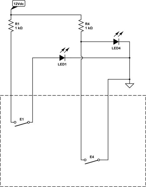
simulate this circuit – Schematic created using CircuitLab

