0
\$\begingroup\$

The following is a question from 8.18 in Design of Analog CMOS Integrated Circuit, page 342.

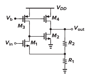
Consider the circuit this following Fig, \$(\frac{W} {L})_{1-4} =\frac{50} {0.5} \$, \$|{I_D}_{1-4}| = 0.5 mA\$, \$R_2 = 3 k\Omega\$.

enter image description here

Calculate the closed-loop gain and output impedance.

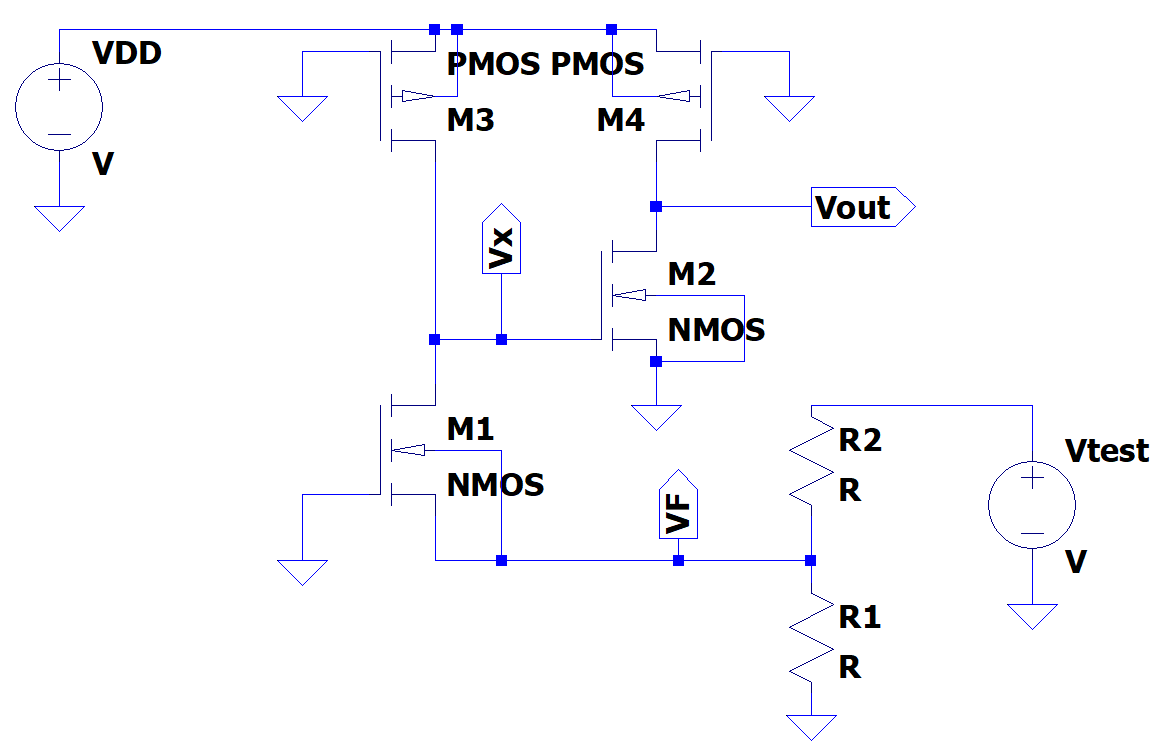
Break the loop and add test voltage.

enter image description here

$$\frac{V_x -V_F} {r_{o1}} - V_F g_{m1} = -\frac{V_x} {r_{o3}}$$

$$\Rightarrow \frac{V_x} {V_F} = (r_{o1} \parallel r_{o3}) (r_{o1} \parallel \frac{1} {g_{m1}})$$

$$- \frac{V_{out}} {r_{o4}} = V_x g_{m2} + \frac{V_{out}} {r_{o2}}$$

$$\Rightarrow \frac{V_{out}} {V_x} = - g_{m2} (r_{o2} \parallel r_{o4})$$

$$\Rightarrow \frac{V_{out}} {V_F} = \frac{V_{out}} {V_x} \frac{V_x} {V_F} = - g_{m2} (r_{o1} \parallel r_{o3}) (r_{o1} \parallel \frac{1} {g_{m1}}) (r_{o2} \parallel r_{o4})$$

$$V_F = \frac{R_1} {R_1 + R_2} V_{test}$$

$$A \beta = \frac{V_{out}} {V_{test}} = - g_{m2} (r_{o1} \parallel r_{o3}) (r_{o1} \parallel \frac{1} {g_{m1}}) (r_{o2} \parallel r_{o4}) \frac{R_1} {R_1 + R_2} $$

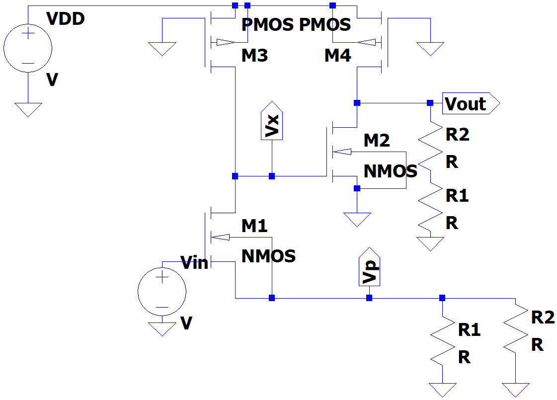
To calculate open loop gain, we can have this circuit.

enter image description here

Between M1 and M3, we have $$-\frac{V_x} {r_{o3}} = \frac{V_p} {R_1 \parallel R_2}$$ $$\frac{V_x - V_p} {r_{o1}} + (V_{in} - V_p) g_{m1} = - \frac{V_x} {r_{o3}}$$

$$\Rightarrow \frac{V_x} {V_{in}} = \frac{g_{m1}} {1 / (r_{o1} \parallel r_{o3}) + \frac{R_1 \parallel R_2} {r_{o1} \parallel \frac{1} {g_{m1}}} }$$

Between M2 and M4, we have

$$- (\frac{V_{out}} {r_{o4}} + \frac{V_{out}} {R_1 + R_2}) = V_x g_{m2} + \frac{V_{out}} {r_{o2}}$$

$$\Rightarrow \frac{V_{out}} {V_x} = -g_{m2} \bigr(r_{o2} \parallel r_{o4} \parallel (R_1 + R_2) \bigr)$$

$$A_{v,open} = \frac{V_{out}} {V_{in}} = \frac{V_{out}} {V_x} \frac{V_x} {V_{in}} = -g_{m2} \frac{g_{m1}} {1 / (r_{o1} \parallel r_{o3}) + \frac{R_1 \parallel R_2} {r_{o1} \parallel \frac{1} {g_{m1}}} } \bigr(r_{o2} \parallel r_{o4} \parallel (R_1 + R_2) \bigr)$$

$$A_{v,close} = \frac{A_{v,open}} {1 + A \beta}$$

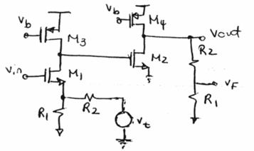
The following is what I found from internet. Is this correct?

enter image description here

$$A \beta = \frac{V_F} {V_t} = \frac{1} {R_2} (R_1 \parallel R_2) \frac{r_{o3}} {(R_1 \parallel R_2) + \frac{1} {g_{m1}}} g_{m2} (r_{o4} \parallel (R_1 + R_2) \parallel r_{o2}) \frac{R_1} {R_1 + R_2}$$

$$A_{v,close} = \frac{r_{o3}} {(R_1 \parallel R_2) + \frac{1} {g_{m1}}} g_{m2} \Bigr(r_{o4} \parallel (R_1 + R_2) \parallel r_{o2} \Bigr)$$

\$\endgroup\$
9
  • \$\begingroup\$ I'm wondering if you realize (by simple and quick visual inspection of the circuit) that the closed loop gain is \$1+\frac{R2}{R1}\$ <-- is this what you are aiming to achieve? I mean, trying to get a very precise formula is kind of missing the point when it comes to real life devices and their variations. \$\endgroup\$
    – Andy aka
    Commented Mar 13 at 13:00
  • \$\begingroup\$ @Andyaka I want to get better results with hand calculation \$\endgroup\$
    – kile
    Commented Mar 13 at 13:12
  • \$\begingroup\$ @kile - I think, for finding the loop gain you forgot the load at the node V_out. More than that, for finding the gain under open-loop conditions you forgot that the load must be (R2+R21||rin) with rin=input resistance at the source of M1. \$\endgroup\$
    – LvW
    Commented Mar 13 at 13:17
  • \$\begingroup\$ @Lvw Do you mean there is resistor feedback network at node \$V_{out}\$? I don't understand what you \$((R_2 + R_1) \parallel R_{in}) \$ is? Why do we need \$R_{in}\$? \$\endgroup\$
    – kile
    Commented Mar 13 at 13:42
  • \$\begingroup\$ @kile - please write rin (and NOT Rin) because rin is a dynamic resistance and it is very important not to mix dynamic/differential quantities with static values. In the 2nd part of your calculations, why do you load the node Vout with (R2+R1) ? This is OK because this node is in fact loaded - however, there is another resistance across R1, is it not? And this resistance (rin) is pretty small (in contrast to the case of an opamp where the inverting input represents a very large resistance, which can be neglected). \$\endgroup\$
    – LvW
    Commented Mar 13 at 14:23

2 Answers 2

2
\$\begingroup\$

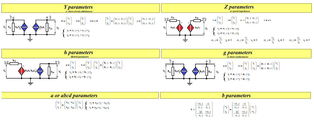
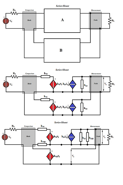
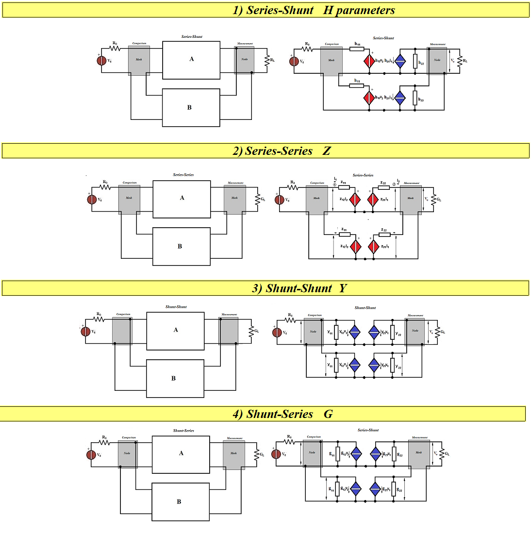
First of all you must identify the class (configuration) to which the feedback amplifier belongs. Then proceed as in one of the examples on the texts indicated in the figure where I also show the page:

enter image description here enter image description here enter image description here

\$\endgroup\$
13
  • \$\begingroup\$ Serie-Shunt for my case. What do you think \$\endgroup\$
    – kile
    Commented Mar 13 at 17:19
  • \$\begingroup\$ The analysis is done after tracing the equivalent circuit for incremental signals or dynamic circuit. Did you draw it? I do not see it! \$\endgroup\$ Commented Mar 13 at 17:46
  • \$\begingroup\$ I think my analysis is equivalent circuit for incremental signals or dynamic circuit. Where will you break the loop? \$\endgroup\$
    – kile
    Commented Mar 13 at 17:53
  • \$\begingroup\$ In the equivalent circuit, each active device must be replaced with its dynamic equivalent circuit. The transistor symbol should be used only in the bias circuit. The open loop gain βA, if I'm not mistaken, does not depend on where you break the loop, i.e., it is always the same wherever you break the loop. \$\endgroup\$ Commented Mar 13 at 18:27
  • \$\begingroup\$ Honestly, I haven't checked your calculations at all. But I would advise you to study the eighth chapter on reaction again. \$\endgroup\$ Commented Mar 13 at 18:34
1
\$\begingroup\$

The indicated text is aimed at those who know electronics and the principles of negative feedback well. The amplifier in question is indeed a feedback amplifier. There are four configurations of a feedback amplifier. The one in question falls into one of these. But without knowing the principles of the reaction one gets lost in more or less correct calculations.

\$\endgroup\$
1
  • \$\begingroup\$ How are you gonna solve this feedback problem? \$\endgroup\$
    – kile
    Commented Mar 13 at 12:28

Your Answer

By clicking “Post Your Answer”, you agree to our terms of service and acknowledge you have read our privacy policy.

Not the answer you're looking for? Browse other questions tagged or ask your own question.