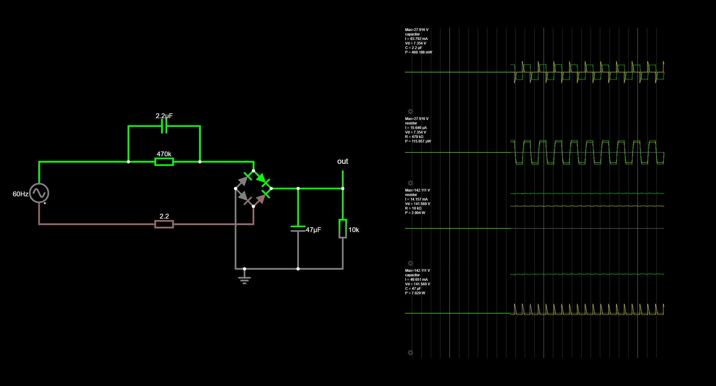
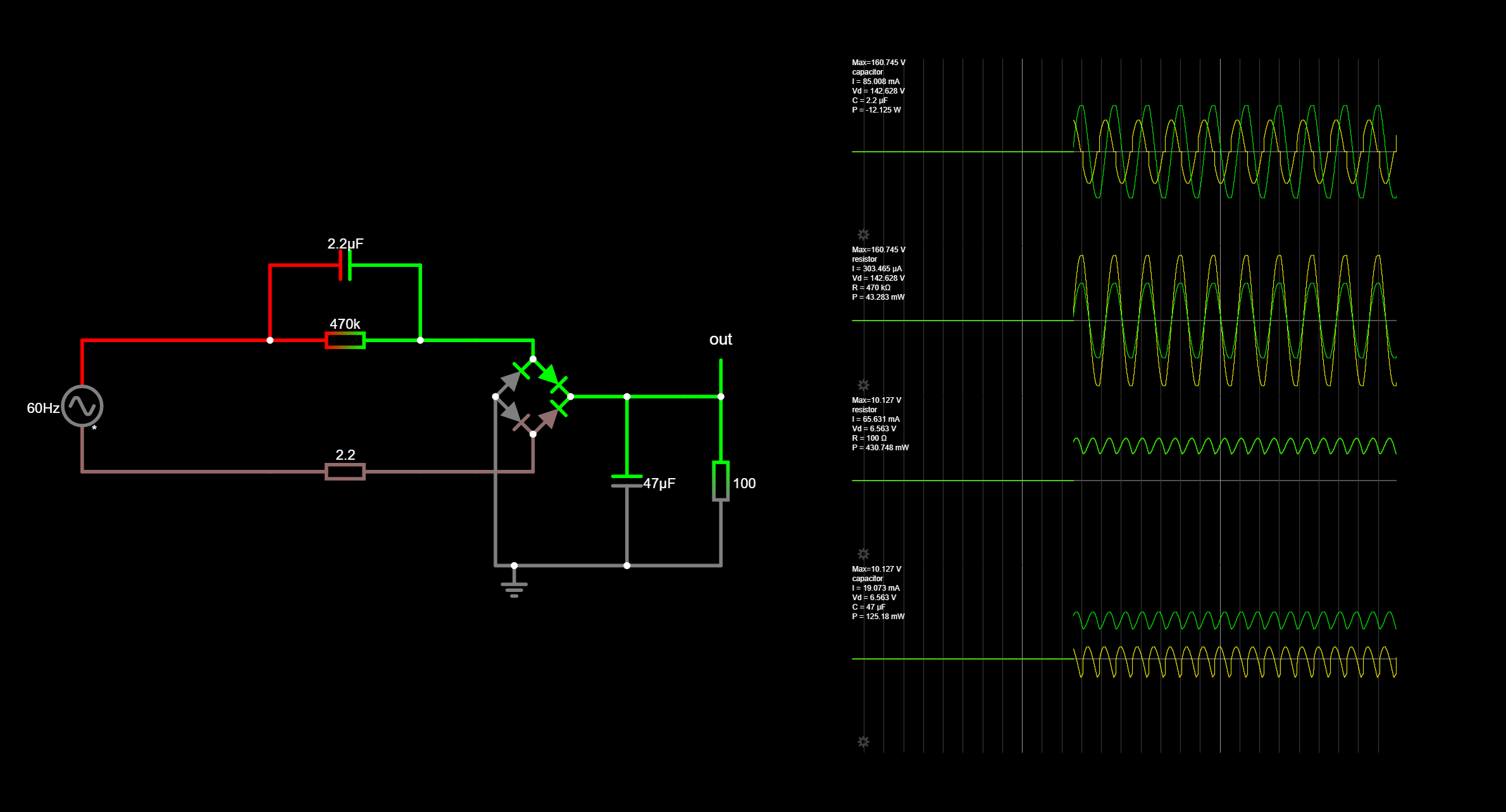
To facilitate a more detailed discussion, consider adding a unique reference designator to each component.
At 60 Hz, each capacitor has a specific impedance. For a simplistic analysis of the circuit, replace each capacitor with its equivalent 60-Hz-resistance. Next, combine any series and/or parallel resistances into their equivalent single-resistor value. Then, with Ohm's Law, you can calculate the voltage drops throughout the circuits as the load resistance changes.
Note that because the input AC is full-wave rectified, the frequency seen by the 47 uF cap is 120 Hz, not 60 Hz. Actually, the frequency spectrum of a full-wave rectified sinewave is more complex (!) than that (you can see this in the very distorted current waveform), but for this analysis it is close enough.
To facilitate a more detailed discussion, consider adding a unique reference designator to each component.


