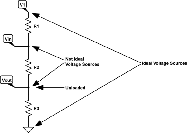
Your schematic with some comments added:

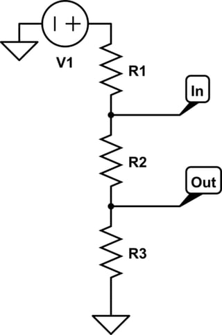
simulate this circuit – Schematic created using CircuitLab
Assuming you leave \$V_{_\text{OUT}}\$ unloaded, then \$V_{_\text{IN}}\$ sees \$R_1\$ going to one ideal voltage source and sees \$R_2+R_3\$ going to another ideal voltage source. So the resulting impedance seen from the point of view of \$V_{_\text{IN}}\$ (\$V_{_\text{OUT}}\$ unloaded) would in fact be just as you said: \$R_1\vert\vert\left(R_2+R_3\right)\$.
You can demonstrate this fact by injecting a \$1\:\text{A}\$ current source into \$V_{_\text{IN}}\$. (There are more mathematical ways -- graph theoretic -- which provide more insight, too. But it would take me longer and I'd rather not spend the time if I can avoid it.) Suppose you don't inject a current and measure a voltage at
\$V_{_\text{IN}}\$ and then inject \$1\:\text{A}\$ and measure a voltage at
\$V_{_\text{IN}}\$, again? The impedance/resistance is the difference between these voltages (divided by \$1\:\text{A}\$ to keep the units correct, but it doesn't make a numerical difference.)
The KCL equation, including the optional injected current, would be \$\frac{V_{_\text{IN}}-V_1}{R_1}+\frac{V_{_\text{IN}}}{R_2+R_3}=I_{_\text{INJ}}\$. This solves out as \${V_{_\text{IN}}}_{(I_{_\text{INJ}})}=\frac{\left(V_1+I_{_\text{INJ}} \,R_1\right)\left(R_2+R_3\right)}{R_1+R_2+R_3}\$. We want to know \$\frac{{V_{_\text{IN}}}_{(1\:\text{A})}-{V_{_\text{IN}}}_{(0\:\text{A})}}{1\:\text{A}-0\:\text{A}}\$. But that's \$\frac{R_1\left(R_2+R_3\right)}{R_1+R_2+R_3}\$. Which also happens to be what you get for \$R_1\,\vert\vert\left(R_2+R_3\right)\$.
You could go further. You could set up two KCL equations with two optionally injected currents, one at \$V_{_\text{IN}}\$ and one at \$V_{_\text{OUT}}\$, and use that to help you see what the impedance at \$V_{_\text{IN}}\$ looks like with differing loads on \$V_{_\text{OUT}}\$. If you need help with that, let me know.
Edit: I left this question hanging for a couple of hours, mid-edit, before finishing it. I see Spehro already answered it now that I finally posted this up. So I guess you have two thoughts. :)


how to show that.? \$\endgroup\$