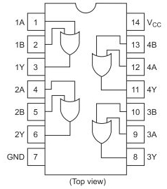
I'm struggling to implement the HD74HC32 (quadruple 2-input positive-OR gate) package:

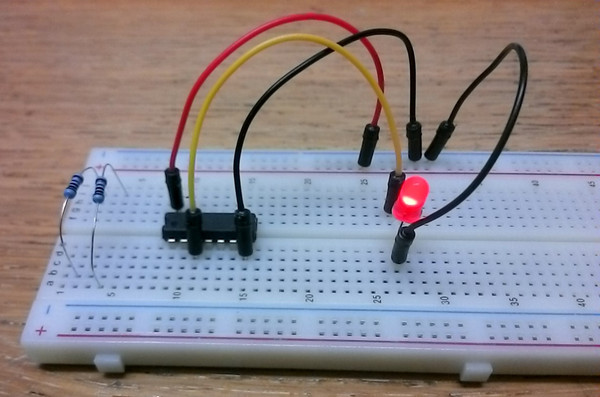
My breadboard looks as following:

Notes:
1.8volt power supply, sufficient according to theHD74HC32datasheet1Ais located at the left bottomVccconnected to[+]andGNDconnected to[-]1Yconnected toLED AnodeLED cathodeconnected to[-]
I tried every possible combination, with and without resistors, but I cannot get the gate to work. The LED even stays on while 1A and 1B are disconnected.
How do I get this OR gate to work as expected?
The following question looks alike, but I just can't get it to work :(
Connecting AND Gate Chip to an Integrated Circuit
My reputation is too low to embed images, that's why linked directly, sorry!

HD74HC32datasheet. I choose the 1.8 volt because I ran out of proper resistors for the LED to work with 5 volt. I'm just "playing around" with logic gates for the first time! \$\endgroup\$