3
\$\begingroup\$

I was thinking of making a die that runs somehow from 1 to 6. Using a decade counter it resets after reaching > 6. But the problem is at that point the pulses from the digital clock may still flow but I need it to for sure hit one pulse right after reset, otherwise it will display a zero. It has to be directly after resetting because if the button is released after 6 it should go to displaying 1, not 0. How to do this?
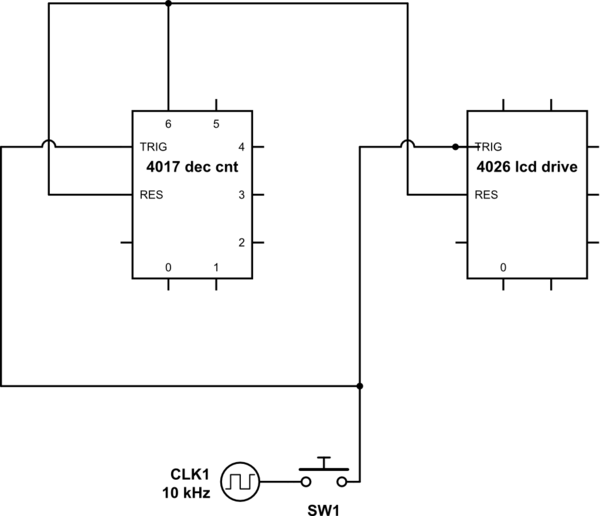
schematic

simulate this circuit – Schematic created using CircuitLab

\$\endgroup\$
12
  • \$\begingroup\$ Yeah. It's easy enough. You don't want to use an MCU? \$\endgroup\$ Commented Sep 29 at 19:38
  • \$\begingroup\$ No the challenge I came up was is doing it without an MCU. MCU is not a challenge... I don't really get the answer from the link though... \$\endgroup\$
    – Niels
    Commented Sep 29 at 19:41
  • \$\begingroup\$ well what i hoped for was that using some kind of RC circuit in between it could be solved, but if not, i am open for suggestions. \$\endgroup\$
    – Niels
    Commented Sep 29 at 19:46
  • 1
    \$\begingroup\$ The 4017B and 4022B are decade and octal counters. That's not what you want. What's the voltage supply? Do you have to have 3-18 V range of operation? \$\endgroup\$ Commented Sep 29 at 19:50
  • \$\begingroup\$ it is 4017 (decade counter) and 4026 is drive a 7 segment lcd display (the old well known '8-module'), voltage sure can be in that range, i will be using a 555 times for the pulses, putting it anywhere about 1 kHz should give semi random results when i push the button briefly. \$\endgroup\$
    – Niels
    Commented Sep 29 at 19:52

2 Answers 2

4
\$\begingroup\$

schematic

simulate this circuit – Schematic created using CircuitLab
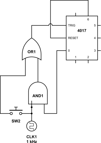
This could be simply done by adding one 2-OR gate and one 2-AND gate.

One AND gate input is connected to the clock while the other to 4017 '0’ out so you get the extra pulse after reset.

Wire one input of the OR gate to the output of the AND gate and the other input to the switch output.

The new triggers are the output of the OR gate.

\$\endgroup\$
2
  • \$\begingroup\$ I don't think we really need the OR, do we? \$\endgroup\$
    – Niels
    Commented Sep 30 at 9:47
  • \$\begingroup\$ For sure: it must be compliant with the logical gate levels... \$\endgroup\$
    – user317139
    Commented Sep 30 at 10:08
1
\$\begingroup\$

trying to add an extra pulse seems tricky, and possibly could cause timing problem between the two chips. probably best to avoid that.

Instead of the 4026 use a counter that has a preload (set to 1) combined with a binary-to-7 segment chip.

for example you could use 4510 and 4511

\$\endgroup\$

Your Answer

By clicking “Post Your Answer”, you agree to our terms of service and acknowledge you have read our privacy policy.

Not the answer you're looking for? Browse other questions tagged or ask your own question.