4
\$\begingroup\$

I am asking this question specifically for buck converter inputs, but am happy to consider answers that are more general -- not specific to buck converter ICs, or focused on the output filter.

Background:

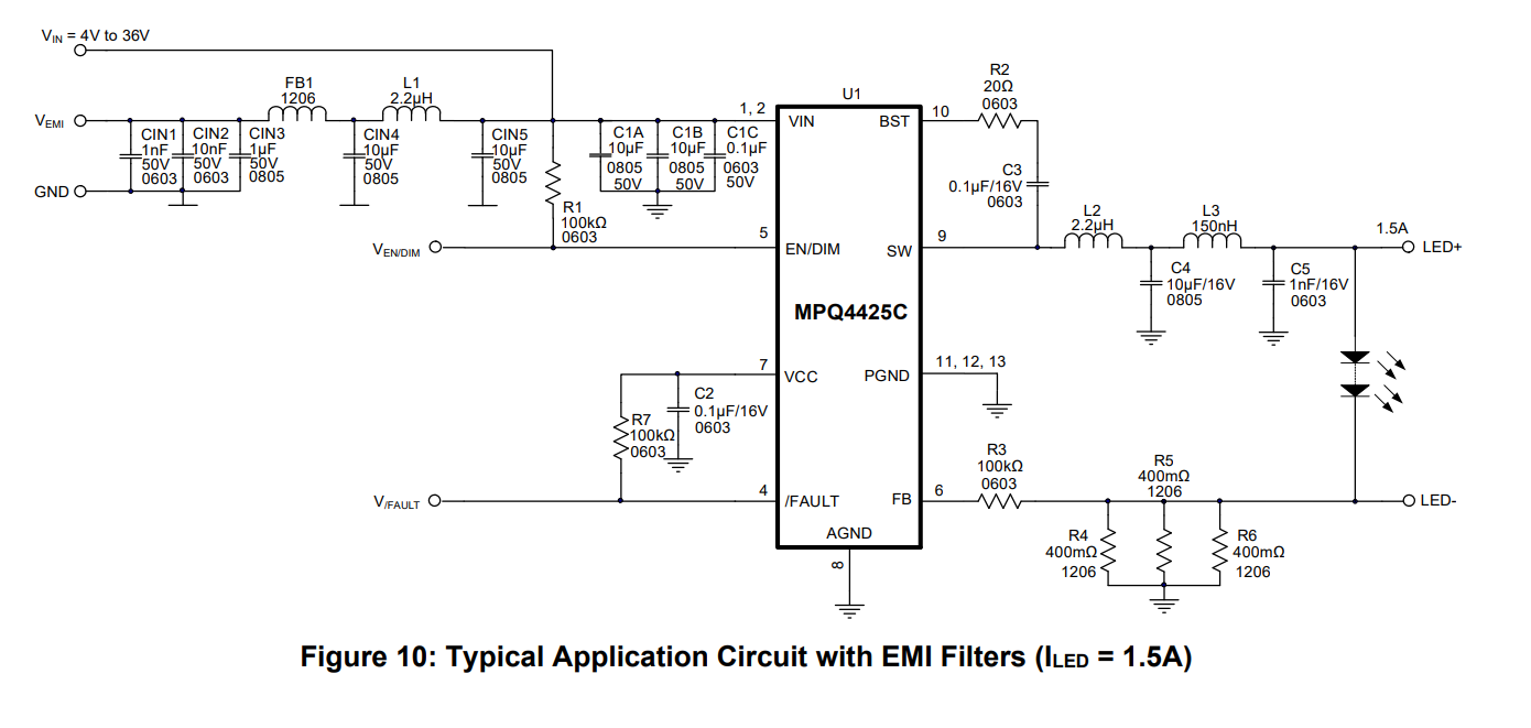
The datasheet of buck converter IC MPQ4425C claims to pass CISPR25 radiated and conducted emissions with a particular EMI filter.

A snippet of the MPQ4425C datasheet which contains the recommended EMI filter, is pasted below. MPQ4425C datasheet snip - EMI filter The datasheet can currently be accessed at the following link: https://www.monolithicpower.com/en/documentview/productdocument/index/version/2/document_type/Datasheet/lang/en/sku/MPQ4425CGQBE-AEC1/document_id/10541/
My framing and assumptions follow:

This EMI filter contains many of the design decisions that I would consider necessary for good buck converter EMI performance. Buck converters have discontinuous input current (square waves of current), so input filtering is important. It has parallel MLCCs on the input, and at least one series attenuating element (here, both inductor and bead), with capacitors on either side of the L for further attenuation. While not strictly true, a device like this is likely to have input wiring that is able to radiate, further necessitating attenuation of voltages/currents on said input nodes.
Buck converters in general have much lower frequency content on the output (triangle waves of current), and as such the output filters and capacitors are less of a threat of EMI.

Thus, I intend to focus on the input of this circuit, but am open to re-framing my assumptions. Ultimately I hope for answers/discussions that get to the crux of the question, which is the decision to place the ferrite bead or the inductor first.

In short:

Cascading LC filters is a way to increase attenuation. Combining two different kinds of inductors, a standard inductor and a ferrite bead, is another way to improve frequency specific attenuation.

But in which order should a ferrite bead and an inductor be placed? What effects might each configuration have -- both functional and relating to EMC? In other words -- what if I swapped FB1 and L1?

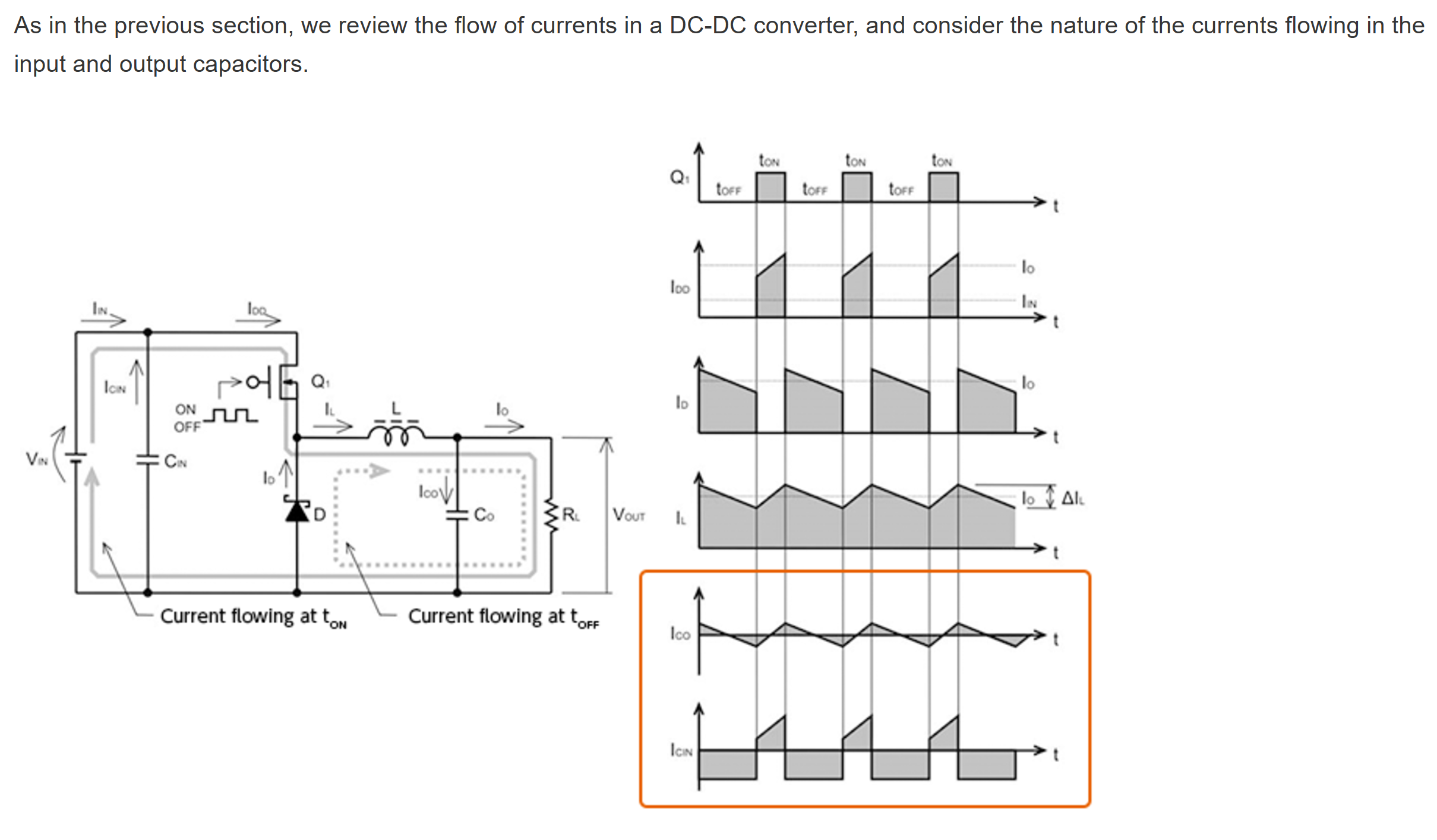
Edit for clarity: Example of buck converter's square-like input current waveform: Observe square-like discontinuity in input current waveforms. buck converter waveforms Source: Rohm website about Input capacitor selection https://techweb.rohm.com/product/power-ic/dcdc/2452/
\$\endgroup\$
7
  • \$\begingroup\$ Firstly, it's not just the filter alone that allows a design to pass radiated emissions; it's also the PCB layout. Secondly, the current into the buck converter is not a square wave but more like a triangular wave. Have you tried simulating the inductor/bead circuit to see how it works in both directions? The filter design for the device is specific to that i.e. you can't expect to use that filter in another circuit and expect that other circuit to pass the EMI regulations so, what is the basis of your question about swapping the bead with the inductor? \$\endgroup\$
    – Andy aka
    Commented Nov 27 at 8:44
  • \$\begingroup\$ @Andyaka, First point: understood. Second point: are you sure?, buck converter inputs are more square like than triangle like, see my edit and observe the sharp square-like edges. Critically, square waves have fourier series with 1/k term, whereas triangle is 1/k^2, meaning considerably less high-f harmonics. Do you agree now? I have simulated it, but I do not trust my ability to simulate beads and pcb parasitics. Understand this is specific to one part, I am just trying to discuss the difference in how the two different "L's" would behave in a practical circuit if they are swapped. \$\endgroup\$
    – rohmeooo
    Commented Nov 27 at 15:02
  • \$\begingroup\$ ok, my mistake, I was thinking if the inductor current (second point) \$\endgroup\$
    – Andy aka
    Commented Nov 27 at 20:07
  • \$\begingroup\$ Have you tried to simulate both? You won't see it all if you have an ideal voltage source feeding it, but you can simulate a LISN to provide the same input as your compliance test. The more difficult part could be to have your inductance roll-off with frequency depending on core material, but just the ideal values alone would give you a starting point. This would address conducted EMI. Radiated is far more dependent on layout. \$\endgroup\$
    – winny
    Commented Dec 2 at 15:14
  • 1
    \$\begingroup\$ Another thing to be aware of, is stability issues when you add a filter to the input of the DC-DC converter. The DC-DC converter can present a negative impedance (Middlebrooks criterium), which combined with a low loss the filter can lead to oscillations than can damage the converter. \$\endgroup\$
    – Tyassin
    Commented Dec 5 at 20:26

1 Answer 1

3
+50
\$\begingroup\$

For the input filter, it's important to have the capacitor close to the supply terminal, with a small loop area to GND. This cap supplies the high-side transient.

This would imply C-L-C-L-C input sequence as shown in the MPQ appnote to be preferred.

Layout matters too: minimize the loop areas for both the main input cap and especially the output cap. The fast currents in these paths have a profound influence on radiated emissions.

Here's a sim to play with (simulate it here):

enter image description here

You can see that the current ripple at the 5V input is pretty well knocked down by the double-pi filter.

But also take note of transient current going to the FET drain. This has that square/sawtooth shape as the FET switches on. At first it jumps up immediately, then ramps up with the inductor current build-up. That initial step is a pretty big dI/dt jump, that's handled by the 10uF cap that's closest to the FET. That cap's performance would be far less effective if it were placed with the inductor in its path.

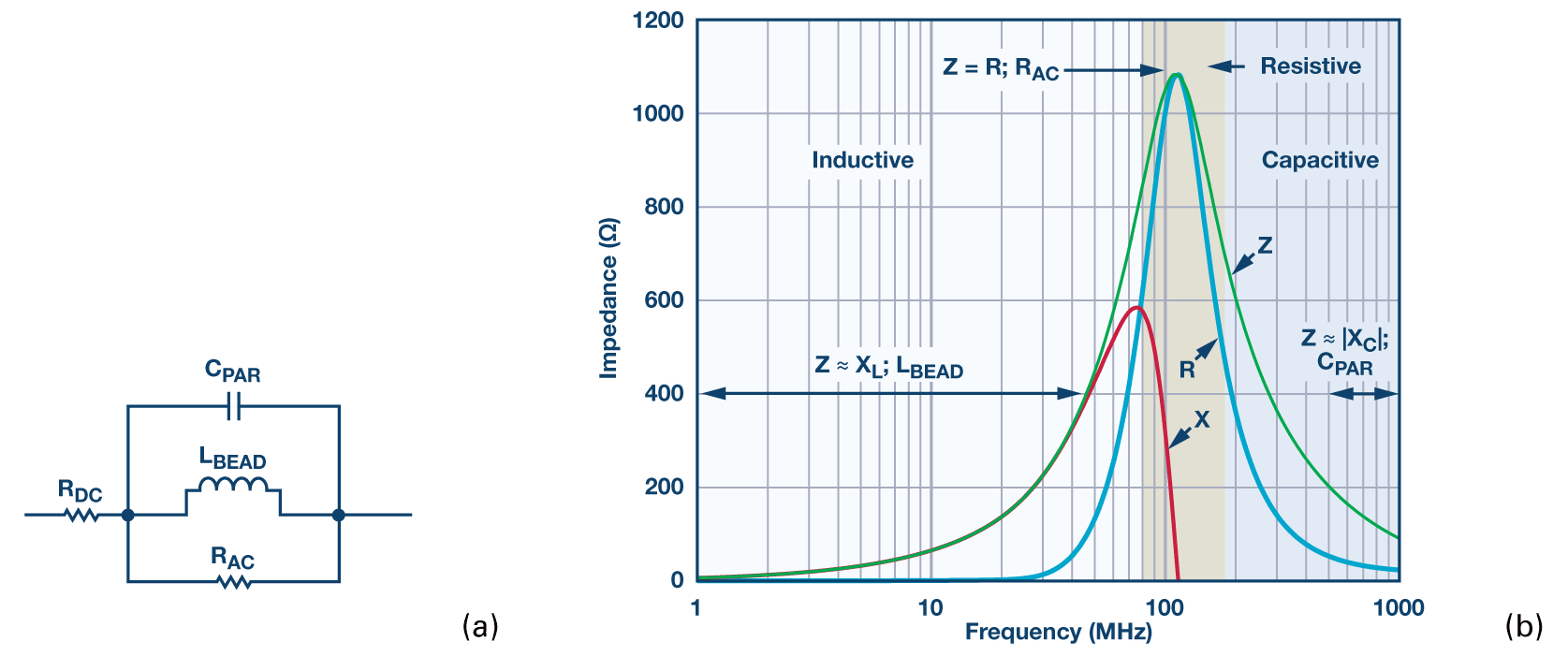
You may be curious how to model a ferrite. The simple model uses 4 components, arranged as below:

enter image description here

From https://www.analog.com/en/resources/analog-dialogue/articles/ferrite-beads-demystified.html

In this article they analyze a selected bead and create a model for it, and show work to optimize its performance with damping.

\$\endgroup\$

Your Answer

By clicking “Post Your Answer”, you agree to our terms of service and acknowledge you have read our privacy policy.

Not the answer you're looking for? Browse other questions tagged or ask your own question.