2
\$\begingroup\$

I am reading about working with virtual ground and generating negative voltage. I am trying to power a differential op amp circuit, and I expect some of these differences to result in a Vout that is negative. Because of this, I wanted to bias my op amp with +5V and -5V.

I only have a positive voltage source, and I am using TinkerCAD to simulate this. I read that I can use things like charge pumps, but I was wondering if it would be possible to implement a virtual ground as a reference ground and anything below this reference point would be negative. So this would make actual ground (0V), be interpreted as -5V, if my virtual ground was 5V and my power supply was 10V.

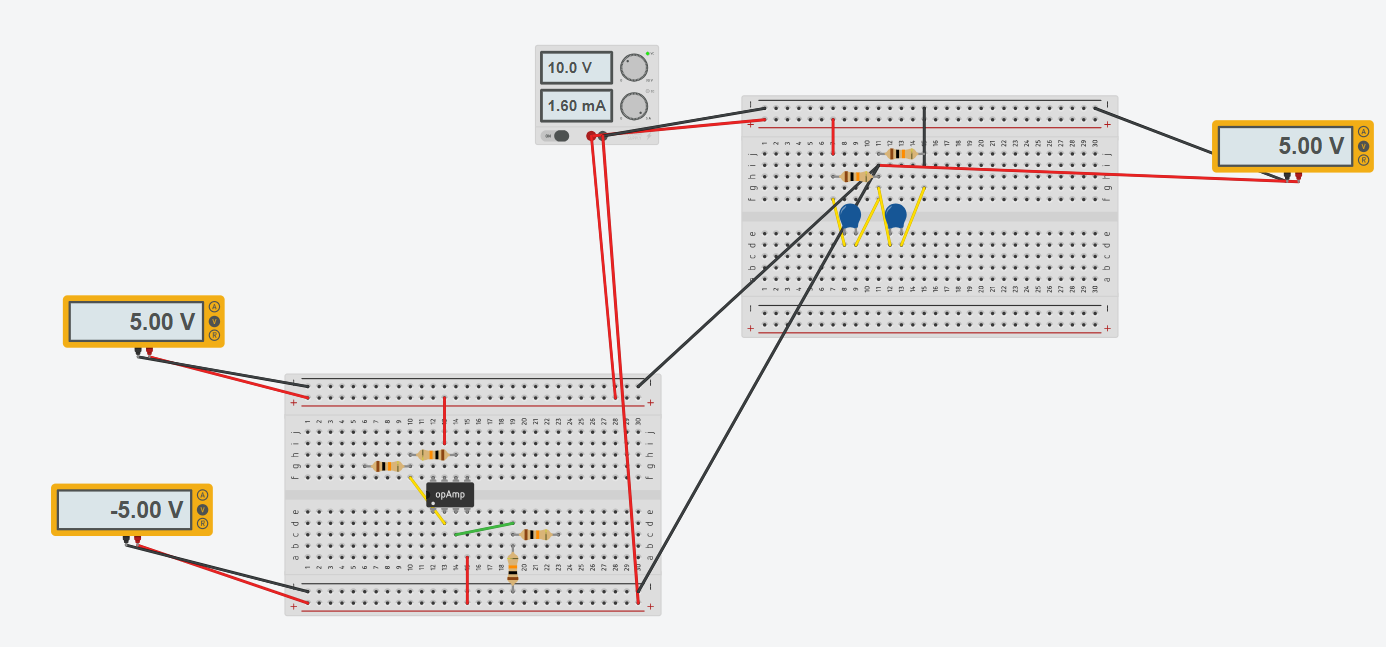
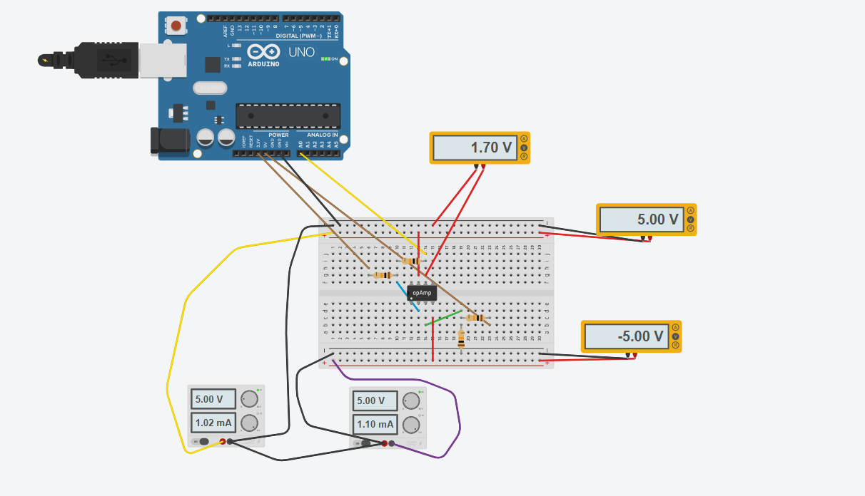
In the first picture, I take two power supplies and put them in series with each other to establish a virtual ground. This seemed to work well, since 5V - 3.3V = 1.7V in the Vout as expected, but I wanted to try to do this with only one power supply

enter image description here

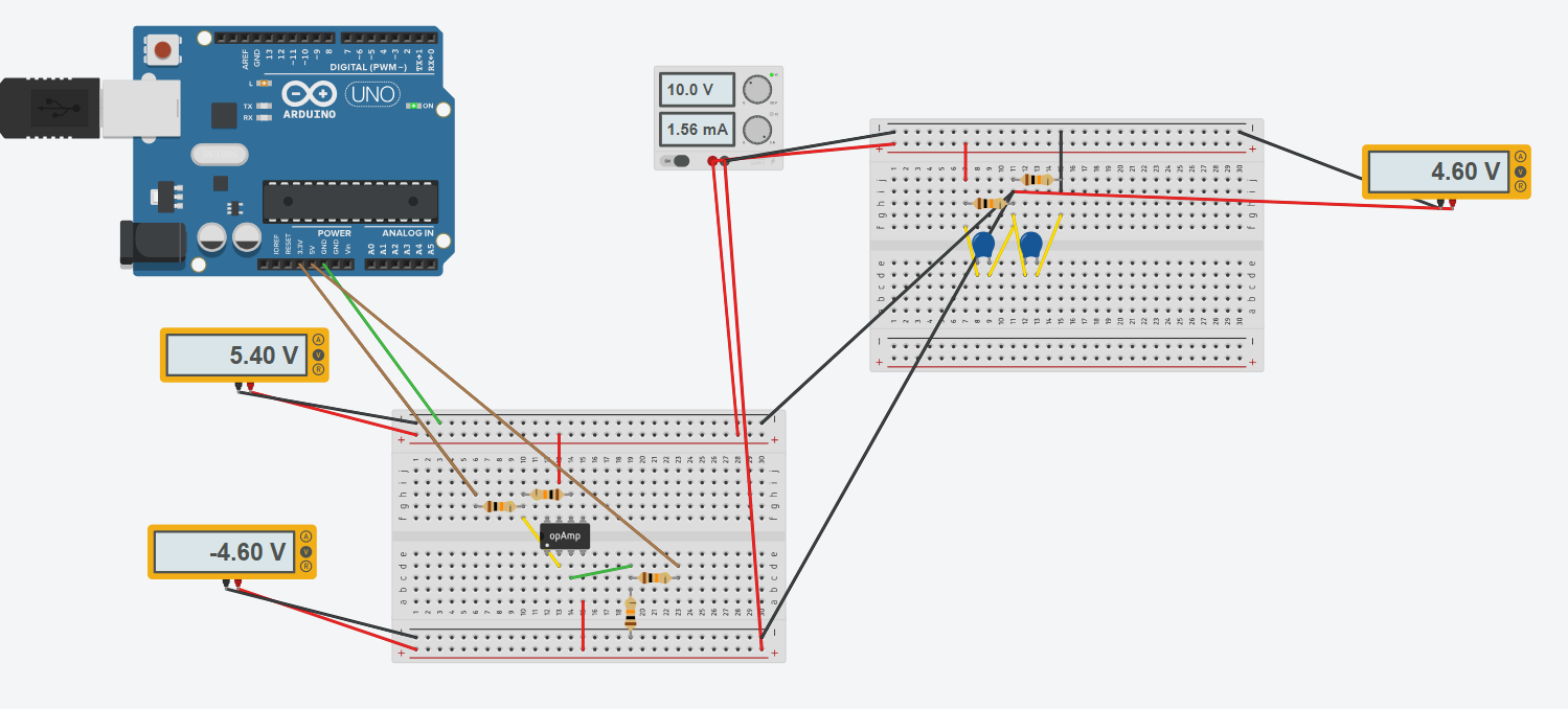
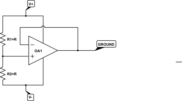
In this second picture, I created a virtual ground (5V) using a voltage divider and two capacitors in parallel (schematic I found online is attached below). I then set the ground of another breadboard to be this new reference, and it seems like the rails are measuring +/-5V as expected.

enter image description here

However, when I connect two voltage sources to then use the differential amplifier (3.3V and 5V), I get a change in voltage readings across all of the rails and I am not sure why, I'd like them to be stable.

enter image description here

I am wondering if someone can help me figure out the issue, or guide me on what steps I should take to troubleshoot. I appreciate any help!

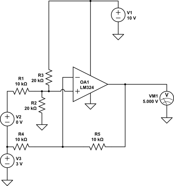
If helpful, this is the differential op amp circuit I was trying to implement: enter image description here Referenced from another stackexchange post: How to Calculate Op-Amp Level Shift for differential amp and gain of 2
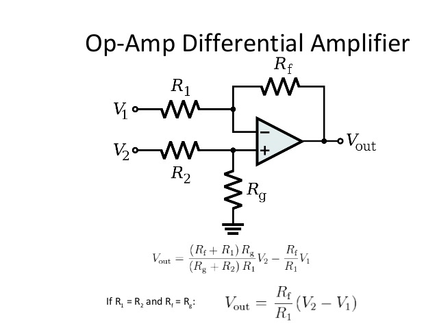
And this is the capacitor and resistors voltage divider circuit I was following online: enter image description here
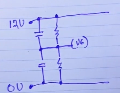
Referenced from learnelectronics on YouTube at time [2:56]: https://www.youtube.com/watch?v=5CaPmKfBhDk&ab_channel=learnelectronics

New contributor
Daniel is a new contributor to this site. Take care in asking for clarification, commenting, and answering. Check out our Code of Conduct.
\$\endgroup\$
1
  • 1
    \$\begingroup\$ The impedance of your artificial (nothing virtual about it) ground is 5 kOhm although it needs to be 0 Ohm at DC for the differential amp to work as expected. These 5 kOhm are in series with Rg which is why you get strange but correct voltage readings. Add another op amp with unity gain that buffers the 5V from the resistive divider. \$\endgroup\$
    – Raonoke
    Commented 6 hours ago

2 Answers 2

0
\$\begingroup\$

In your circuit the current passing through Rg will affect the voltage Vg at the voltage divider. The Thevenin equivalent source resistance is R/2 so if you have 10kΩ resistors as shown in your pictorial diagram the source Z is 5kΩ. That will reduce the gain from V2 quite significantly, leaving the gain from V1 unaffected. You could forget the divider and replace Rg with two 20k resistors, one from the input to each supply, then the output would be 5V for 0V differential input.

schematic

simulate this circuit – Schematic created using CircuitLab

For the circuit shown above, the output voltage is V2+5V and V3 cancels out, over some range.

You could also buffer the 'virtual ground' voltage with another op-amp, and that will work well at DC, however op-amps have significant output resistance for AC. You can add some circuitry to reduce that but it has to be a bit more complex than just capacitors, which will cause most op-amps to be unstable. There are 'rail splitter' ICs that are designed for this task, however it's probably cheaper to add a -5V supply.

It's often better to add a charge pump like the 7660 since that will allow you to have a solid ground that is common with your MCU, and the exact values of your power supply voltages don't affect the output voltage significantly.

\$\endgroup\$
0
\$\begingroup\$

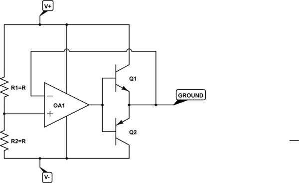
What you are looking for is called a "rail splitter". It takes a single-ended voltage supply and provides an output that "splits" the difference, providing a ground.

The simplest version of a rail splitter is a simple op-amp with a voltage divider providing half the supply voltage at the non-inverting input, and the inverting input set up as a voltage follower, like so

schematic

simulate this circuit – Schematic created using CircuitLab

The major shortcoming of this rail splitter is that it has very limited current capability.

The current capability can be increased with push-pull pair of transistors to boost the current.

Here is the basic form, but there are many improvements that can be made. I'm not going to show them all. Perhaps someone else will show some other options.

schematic

simulate this circuit

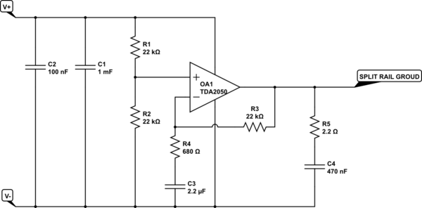
However, I would also like to suggest a third option, which can give you significant current, and may also have significant other advantages. That is to use an audio amplifier IC.

schematic

simulate this circuit

Although the TDA2050 is obsolete in the US, it is manufactured in plentiful supply in China, is quite robust, and inexpensive, and with a heatsink is rated to handle over 3 amps of output current.

R3, R4 and C3 are needed for stability, as the TDA2050 is not unity gain stable. However, the charging of C3 may result in a lopsided "split" as the circuit powers up. If this is an issue, you may want to add some more circuitry.

C4 and R5 may not be necessary. They implement a low pass filter that is present in virtually all audio amps of this topology. Since the output voltage is ideally a constant value half way between the rails, such a filter may be redundant. I have kept this filter in place in case it adds something to the stability of the circuit.

C1 and C2 should be as close to the TDA2050 as possible.

There are commercially available modules implementing this circuit with extra components. In particular, these modules contain an output capacitor that must be removed or bypassed if the module is to be used for rail splitting rather than audio amplification. These modules generally also come with a potentiometer, input capacitors etc. which do nothing for this application, but don't hurt if they are left in place.

Be aware that the pins of a TDA2050 do not fit in a standard solderless breadboard in any reasonable way. So, for prototyping, it is easiest to simply remove/bypass the output cap on a pre-made module.

\$\endgroup\$

Your Answer

By clicking “Post Your Answer”, you agree to our terms of service and acknowledge you have read our privacy policy.

Not the answer you're looking for? Browse other questions tagged or ask your own question.