9
\$\begingroup\$

I want to wire the hotshoe of my dslr (Nikon D5100) to my Arduino board in order to react to the shutter release of the camera.

Nikon Hotshoe schematic

I measured a 5 to 8 volts signal between the trigger and the ground lugs when I push the shutter release. So my question is, if I wire the trigger lug to a digital input of the Arduino, where should I wire the ground lug to ? And subsequent question, do you think I should fear for my camera with the current/voltage involved?

I am fairly new to electronics, so I hope my question doesn't sound too stupid.

\$\endgroup\$
3
  • \$\begingroup\$ Are you sure you measured 8 volts? It should be standard TTL voltages (<5V). See this article: dptnt.com/2010/04/nikon-flash-interface \$\endgroup\$
    – JYelton
    Commented Jul 11, 2013 at 21:56
  • 1
    \$\begingroup\$ And your question doesn't sound stupid. For a newbie, it's a fairly thought out question. \$\endgroup\$
    – Passerby
    Commented Jul 11, 2013 at 23:35
  • \$\begingroup\$ @JYelton: Thank you for the article, I'll have to do some more measurements to confirm that 8v value it seems. \$\endgroup\$
    – Duom
    Commented Jul 12, 2013 at 12:05

3 Answers 3

5
\$\begingroup\$

While the suggested optocoupler is certainly a safe thing to try you may find it doesn't work. Traditionally SLR hot shoes were a simple switch to fire the flash and while modern DSLR systems no longer use the high voltages that some older flashes presented to the camera many use a transistor to pull the line to ground.

Any voltage present on the pin may be via a high-value pull-up or possibly some very low current leakage and not capable of delivering the 5mA odd required to drive an optocoupler. That may explain your somewhat variable readings which I'd expect to be stable if the line was driven hard.

Here's an example of the circuit used within the Camera Axe camera / flash triggering system that may be indicative of what you'd find within the camera:
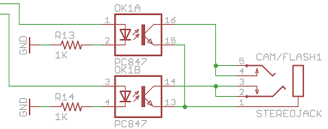
Camera Axe output driver

I didn't have a D5100 available for testing but measuring a family member's Nikon D7000 and my Canon 5D Mark III no voltage was present on the hot shoe. In both cases measuring the flash while detached from the camera but powered up gave a reading of around 5V so it appeared both systems used a pull-up within the flash. I'd suggest a circuit such as the following that I just tried with both:
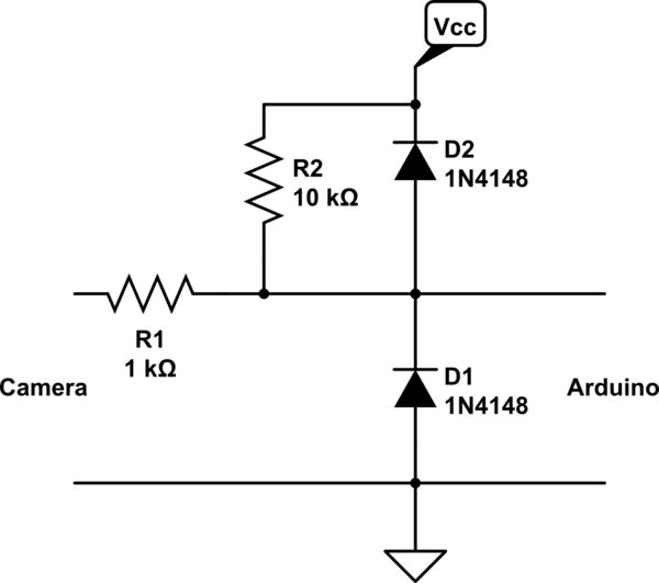
schematic

simulate this circuit – Schematic created using CircuitLab

R2 could be omitted if you use the internal pull-up on the input line while the diodes just give a little extra protection against ESD and over-voltage situations rather than relying solely on the clamps within the AVR. Here's an example of the measured signal for a 1/10 second exposure using that circuit:
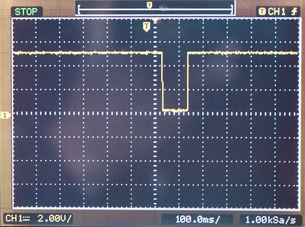
Flash hotshoe measured signal

\$\endgroup\$
7
  • \$\begingroup\$ Thank you for the answer! I have several questions for you though... - I have some troubles understanding the circuit, I placed some bubbles on the schematic where I'm not really sure where the wires are supposed to go could you help me figure that out ?: circuitlab.com/circuit/8hnshs/dslr-to-arduino - You are referring to the pull-up, I'm not familiar with that concept, do you mean "pull up resitor"? as in electronics.stackexchange.com/questions/7423/… \$\endgroup\$
    – Duom
    Commented Jul 14, 2013 at 18:11
  • \$\begingroup\$ Yes it's the same. An AVR used on the Arduino can be programmed to use an internal one, but if unsure how to do it for the sake of a resistor the external one will do the same job. \$\endgroup\$
    – PeterJ
    Commented Jul 14, 2013 at 21:00
  • \$\begingroup\$ Okay, I'll go with the external solution. So if I understand the circuit properly, when the flash is triggered the current will flow through R1 then D2 and R2 which will produce the voltage drop. \$\endgroup\$
    – Duom
    Commented Jul 15, 2013 at 11:13
  • \$\begingroup\$ R2 doesn't drop the voltage, it's called a pull-up (you'll find questions here about how it works) and it means when the input is open the I/O line is a known state, but can still be pulled low by the camera. R1 limits the current a bit so that D1/D2 can cope with over-voltage, like static or if the camera does output a voltage above/below the AVR voltage (it's called a clamp). I think the confusion is imagining the hot shoe as a voltage output. I expect what you're measuring is a small leakage current, think of it like a simple switch and it should be clearer. \$\endgroup\$
    – PeterJ
    Commented Jul 15, 2013 at 11:28
  • \$\begingroup\$ I read some explanations about pull-up, I think I understand it better now. Still if I see the camera as a switch, I should then read high on the arduino and low when the camera is triggered, no ? I did the schematic in a simulator and that's what I read: goo.gl/ljHdN \$\endgroup\$
    – Duom
    Commented Jul 15, 2013 at 17:33
4
\$\begingroup\$

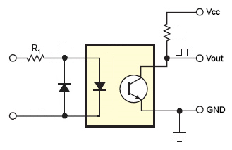
A simple optocoupler would be the best bet, to protect both sides. The led side would be connected to the trigger and ground of the hot-shoe, while the other side is connected to the arduino.

enter image description here

The Resistor on the arduino side is a weak pullup to the arduino power supply. You could skip it if you enable the internal pullup instead, in which case you do not wire the vcc/resistor part.

In this case, when the hotshoe is triggered, the optocoupler enables it's transistor, and the arduino would register a change from logic High, to logic Low.

\$\endgroup\$
3
  • \$\begingroup\$ This sounds like a good safe thing to try, I wonder though on the camera end up how strong the pull-up is and if it would be enough to drive the optocoupler? I'm not sure but I know someone with a D5100 and might have a chance to measure it over the weekend. \$\endgroup\$
    – PeterJ
    Commented Jul 12, 2013 at 11:16
  • \$\begingroup\$ Thanks a bunch for the quick answer! I wouldn't have thought about that, I'll try it as soon as possible. \$\endgroup\$
    – Duom
    Commented Jul 12, 2013 at 12:12
  • \$\begingroup\$ @PeterJ I'm sure you can get the 5ma or so needed to trigger the optocoupler without an issue. \$\endgroup\$
    – Passerby
    Commented Jul 12, 2013 at 12:33
0
\$\begingroup\$

I've been using @PeterJ answer for a time-lapse camera controller, and it works perfectly. However, some applications (like mine), are battery-powered and require very low power on standby. If this is combined with a camera that is powered off during standby by a low-side switch, the circuit suggested by PeterJ leads to a current loss of about 0.1mA. This is because the camera works with 7.4 volts and the controller with 3.3V. And when the camera is powered off (by switching ground) the central contact of the hotshoe pin stays at 7.4V (at least that's the behaviour of an Olympus E-M5 camera). Leading to a current flowing through the diode clamp.

In this case, an alternative circuit would be something like this

enter image description here

It still protects from high voltages but stops any current flowing in such case. If anyone thinks this circuit has a weaknesses I'm not seeing compared to PeterJ suggestion, please comment.

\$\endgroup\$

Your Answer

By clicking “Post Your Answer”, you agree to our terms of service and acknowledge you have read our privacy policy.

Not the answer you're looking for? Browse other questions tagged or ask your own question.