40
\$\begingroup\$

There're such things as transposition towers in power distribution powerlines. The idea is that for example you have three conductors running in parallel at the same height and the leftmost of them is phase A and after transposition the middle one is phase A and the leftmost one in now phase C and phase B which originally was the middle conductor is now the rightmost one. Wikipedia says it's needed because

The transposing is necessary as there is capacitance between conductors, as well as between conductors and ground. This is typically not symmetrical across phases. By transposing, the overall capacitance for the whole line is approximately balanced.

I don't get it. It's three wires in parallel before the transposition and three wires in parallel after the transposition and the distances between the wires are the same before and after the transposition (and the distance between the wires and the ground can hardly even be controlled because ground surface is uneven and changes over time).

How does transposing three parallel wires into three parallel wires help balance the line capacitance?

Edit: Buried in the comments of one answer is a link to a picture highlighting the arrangement of the phases on the transposition tower in the wikipedia article linked above. The picture deserves being shown here...

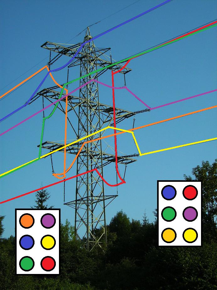
Transposition tower, with the phases highlighted

\$\endgroup\$
1
  • \$\begingroup\$ If anyone is interested, I have written quite a long article on the effects of phase transposition on current asymmetry at a wind farm. It is a 33kV underground cabled system, but it gives a good picture of the real improvements that can be made to balance the three phase currents \$\endgroup\$
    – user124790
    Commented Sep 26, 2016 at 2:03

4 Answers 4

35
\$\begingroup\$

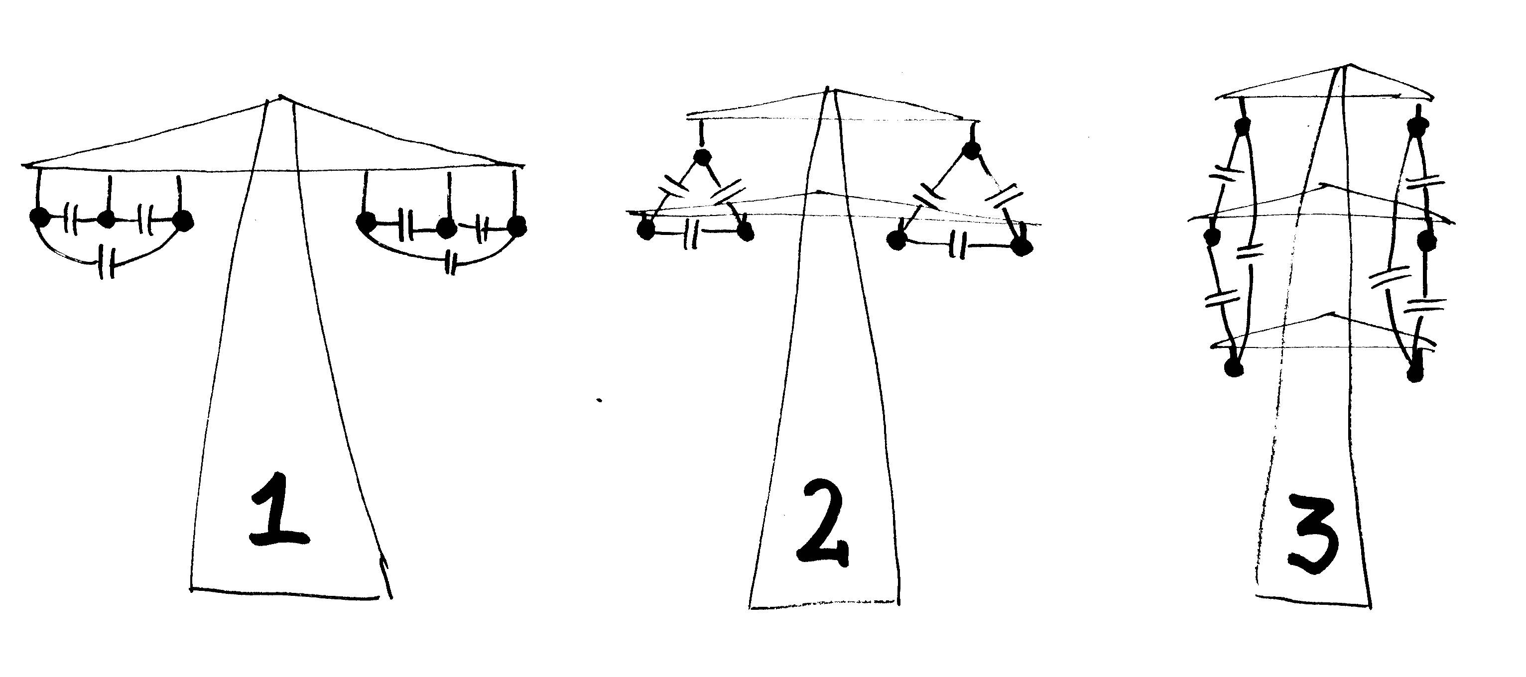
The picture shows three common arrangements of wires. I added wire-to-wire capacitor symbols, note that you also have a wire-to-ground capacitance for each wire. Capacitor values decrease as the distance between the wires increases.

Wire-to-Wire Capacitance Picture is own work, CC BY-SA 3.0

Case 1, Three wires in one level (equal distances to ground, but different wire-to-wire distances):

The capacitance from the middle wire to the two wires on the sides is bigger than the capacitance between the two wires on the outside of the system.

Overall, you want to have an approximately equal capacitance from each wire to the two other wires. Thus, by transposition of the wires, you create, in average, an equal distance (and capacitance) between all wires with respect to each other.

Case 2, Three wires arranged as a triangle (equal wire-to-wire distances, but different distances to ground):

Over the entire length of the system, the distances and capacitance values of the three wires with respect to each other are equal, but the wire-to-ground capacitance is bigger for the wire(s) closer to ground.

By having the three wires swapped over using transposition, each wire spends an equal averaged distance to ground. Thus, the wire-to-ground capacitance values match for the three-phase system.

Case 3, Wires neither spaced equally with respect to each other nor to ground

Now, you end up with two reasons for transposition along the total run of your line.

\$\endgroup\$
2
  • 2
    \$\begingroup\$ Question... In the image of the wikipedia article, if I am interpreting it correctly (my interpretation i.imgur.com/c0ySz9j.jpg), it does not permute the left and right sides in the same way. Why is this? Also, does the (I assume grounded at each pole) wire at the top have any effect on the "capacitance with ground"? \$\endgroup\$
    – Random832
    Commented Sep 23, 2013 at 18:17
  • \$\begingroup\$ @Random832 Wow, great job on that picture! There likely is some reason behind it. Without diving into the details, there is certainly a smaller effect between the two three-phase systems (and the lightning wire on top). If you call your two systems A and B, and their phases A.L1, A.L2, A.L3, B.L1, B.L2 and B.L3, there will also be some capacitive coupling between all of them. For two similar systems, A.L1-B.L1, A.L2-B.L2 and A.L3-B.L3 will be at similar voltages at any given time, so they won't matter considerably. The other wires should have equal coupling, e.g. for A.L1-B.L2 and A.L1-B.L3. \$\endgroup\$
    – zebonaut
    Commented Sep 23, 2013 at 18:43
13
\$\begingroup\$

This is the same concept as behind twisted pair wires. Two wires running parallel will couple differently to the environment because they are on different sides. By twisting them, you average out the external coupling to be about the same from each wire to the environment.

It's a little more complicated when you have 3 wires because you also want to balance coupling between the wires too. By twisting the three wires periodically, each of the wires is treated equally with respect to coupling to ground, the other wires, and anything else around. Radiation into space is also a issue with large power lines. Again, you want all effects to be equal between the three conductors.

Power lines don't appear twisted at first glance because the pitch of the twisting is miles. You want the twist pitch to be a small fraction of a wavelength and there to be anough twists in a line so things even out well. At 60 Hz, a few miles is still a "short" distance.

\$\endgroup\$
5
\$\begingroup\$

From B.M. Weedy's Electric Power Systems 3e (emphasis mine):

Unsymmetrical conductor spacing results in different inductances for each phase which causes an unbalanced voltage drop, even when the load currents are balanced. The residual or resultant voltage or current induces unwanted voltages into neighbouring communications lines. This can be overcome by the interchange of conductor positions are regular intervals along the route, a practice known as transposition.

I have seen transmission line designs which called for uneven spacing of the conductors (i.e. at +1200mm, +375mm, and -1200mm along the cross-arm of a T-shaped wooden pole.

\$\endgroup\$
1
  • 1
    \$\begingroup\$ From a private interview with a transmission design engineer, this outgoing interference problem is the main reason for regular transposition. The other effects can be compensated for at the end of the transmission line, or with minimal transpositions. \$\endgroup\$ Commented Sep 24, 2013 at 8:24
1
\$\begingroup\$

Suppose you have three wires in a horizontal plane: . . .

The middle wire is adjacent to two other wires. Thus, it will be affected differently than the wires on the end. So you want each wire to be in the middle for some distance, so that the effects balance out.

It's also common to have three wires vertically:

.
.
.

In this case, one of the wires will be closer to the ground than the other two, in addition to the fact that one of the wires is between two wires and the other two are not.

\$\endgroup\$

Your Answer

By clicking “Post Your Answer”, you agree to our terms of service and acknowledge you have read our privacy policy.

Not the answer you're looking for? Browse other questions tagged or ask your own question.