4
\$\begingroup\$

I'm transmitting data from a microcontroller to a smarphone mic input and I was suggested to use this circuit to adapt the 5v digital signal:
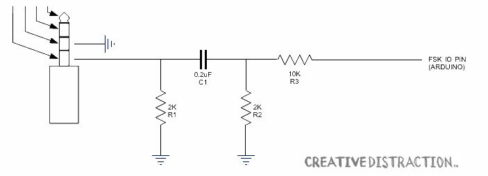
1 Taken from this tutorial

The way I see it R2 and R3 have effect on the filter but their main function is to scale down the signal to aproppiate levels. The circuit is clearly a high-pass filter and I think its only function is to eliminate the DC offset. But why would they do it if the audio input does the AC coupling itself?

\$\endgroup\$
1
  • 1
    \$\begingroup\$ How can you be sure the audio input does ac coupling? If it directly wires to an electret microphone then there will be dc superimposed. \$\endgroup\$
    – Andy aka
    Commented Oct 21, 2013 at 7:29

1 Answer 1

3
\$\begingroup\$

I was going to comment on the schematic being backwards (usually we like to see signals flow from left to right) but perhaps it is appropriate in this case.

Typically the phone supplies a voltage (through a pullup resistor or other current source) to bias an electret microphone, as Andy suggested in his comment. C1 isolates the bias voltage output by the phone from the DC offset of the attenuated Arduino output.

But iPhones (and perhaps other smartphones) also measure the loaded output bias voltage voltage to detect the presence of an external microphone. That's why you need R1- to load the DC source in the phone. Here is a description of the operation.

\$\endgroup\$

Your Answer

By clicking “Post Your Answer”, you agree to our terms of service and acknowledge you have read our privacy policy.

Not the answer you're looking for? Browse other questions tagged or ask your own question.