10
\$\begingroup\$

I have a relay operated by an NPN transistor that needs some voltage applied to the base. I'm working with an arduino and if I give it a digital port, all's well. The circuit looks like this one:
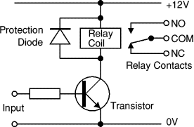
enter image description here

Now I want to replace the arduino port with a DS2406 (the TO92 kind).

This seemed to get really complicated fast. My library for operating the 2406 is fine, but I can't figure out how to wire it.

Now that both pieces independently work, my goal is to get some current fed into the base of the transistor so it throws the relay.

I've run into the following issues:

The DS2406 closes to ground. That's the only option, so I can't map it directly to the base pin of the transistor.

The TO-92 package doesn't have a vcc pin, so I have to have a pull up resistor between vcc and the data pin. This causes stuff to get hot and smelly when I power it up hooked up to the collector of the transistor with the base wired to the relay power. I could be using the wrong kind of resistor, but I don't have a strong sense of what's right here.

I may be able to run the relay strictly off the DS2406, but I'm afraid it will have too much draw, which is why I want it to go through the transistor.

What's the easiest way to go from a switch that opens and closes ground to a transistor base that wants current?

\$\endgroup\$
1
  • \$\begingroup\$ From the title I thought you wanted to perform surgery on the transistor :-) \$\endgroup\$ Commented Jun 15, 2011 at 10:12

3 Answers 3

10
\$\begingroup\$

Your basic NPN transistor switch circuit is an inverter, if you put a pull-up resistor (maybe 10k?) between the collector and 5V. (i.e. the resistor replaces the relay in your linked diagram) When you switch on the base of the transistor (put it to 5V), the voltage at the collector goes to ~0V, and when you switch off the base (0V), the voltage at the collector goes to 5V.

So you could stick such a transistor inverter in between the DS2406 and the transistor driving the relay.

I still think you should be able to use the DS2406 with only one transistor though. Perhaps if you had a pull-up resistor (10k) going from the transistor's base to 5V. This keeps the transistor turned on, unless the DS2406 pulls the base down. Also, don't forget to put the current limiting resistor at the front of the base. If you don't have this, the transistor will "get hot and smelly" as you say. ;)

\$\endgroup\$
4
  • \$\begingroup\$ Thanks for your help. I did get it working without the additional transistor (though it runs backwards from what my switch readings say -- I think that makes sense). I don't completely understand what you mean by the "current limiting resistor", though. That sounds like it'd be in parallel with the pull-up resistor? I have pull-up power for the DS2406 and pull-up power for the transistor base. \$\endgroup\$
    – Dustin
    Commented Dec 6, 2009 at 6:19
  • \$\begingroup\$ In the diagram you linked there's a resistor connected between the input on the left and the base of the transistor. Usually the value of this resistor is about 1k when using the transistor as a switch. \$\endgroup\$
    – todbot
    Commented Dec 6, 2009 at 6:49
  • \$\begingroup\$ Ah. I didn't read that as a resistor (really new at electronics). This is the circuit that is working, but I'd appreciate someone warning warn me of risks of explosion. Nothing smells funny. :/ skitch.com/dlsspy/nkmma/ds2406-controlled-relay \$\endgroup\$
    – Dustin
    Commented Dec 6, 2009 at 7:06
  • \$\begingroup\$ The base current for the NPN comes from the pullup, doesn't it. When the OD output closes, base is at ground and there's no current. I don't think you need further limiting or did I miss something? \$\endgroup\$
    – XTL
    Commented Jun 29, 2010 at 5:45
4
\$\begingroup\$

You could also change your transistor from a NPN to a PNP.

\$\endgroup\$
4
\$\begingroup\$

If you want the relay to close when the DS2406 output closes:

replace the NPN transistor with an equivalent PNP,
tie the PNP's base to the +12V supply through maybe 10k to 50k ohms.
tie the PNP's base to the DS2406 output through maybe 4.7k to 5.1k ohms.

When the DS2406 is high impedance, the first resistor biases the PNP off. When the DS2406 output goes to zero, it pulls about 2mA of current through the base of the transistor and the relay should close.

If you want the relay to close when the DS2406 output opens:

tie the base of the NPN transistor to +12V through about 5k ohms.
connect the output of the DS2406 directly to the base of the NPN

When the DS2406 is high-Z, the resistor should dump about 2mA into the NPN, turning it, and the relay both on. When the DS2406 goes to ground, it will 'steal' that 2mA from the base of the NPN and turn it and the relay off.

The above resistor values are all calculated assuming that 1.5 or 2mA of base current is enough to drive the transistor into saturation. The collector-emitter drop should either be the full supply voltage in the OFF state, or something around 0.2V in the ON state. If not, resistor values should be changed.

\$\endgroup\$

Your Answer

By clicking “Post Your Answer”, you agree to our terms of service and acknowledge you have read our privacy policy.

Not the answer you're looking for? Browse other questions tagged or ask your own question.